Intelligent centrifugal quick extraction device and extraction method of stem cells
An extraction device and stem cell technology, which are applied in the field of intelligent centrifugal rapid extraction devices for stem cells, can solve the problems of residual placental residues, affect the extraction effect, and cannot be cleaned in time, and achieve the effect of ensuring the extraction effect and relative sealing.
- Summary
- Abstract
- Description
- Claims
- Application Information
AI Technical Summary
Problems solved by technology
Method used
Image

Examples
Embodiment Construction
[0034] The following will clearly and completely describe the technical solutions in the embodiments of the present invention with reference to the accompanying drawings in the embodiments of the present invention. Obviously, the described embodiments are only some, not all, embodiments of the present invention. Based on the embodiments of the present invention, all other embodiments obtained by persons of ordinary skill in the art without making creative efforts belong to the protection scope of the present invention.
[0035] As introduced in the background technology, there are deficiencies in the prior art. In order to solve the above technical problems, this application proposes a stem cell intelligent centrifugal rapid extraction device
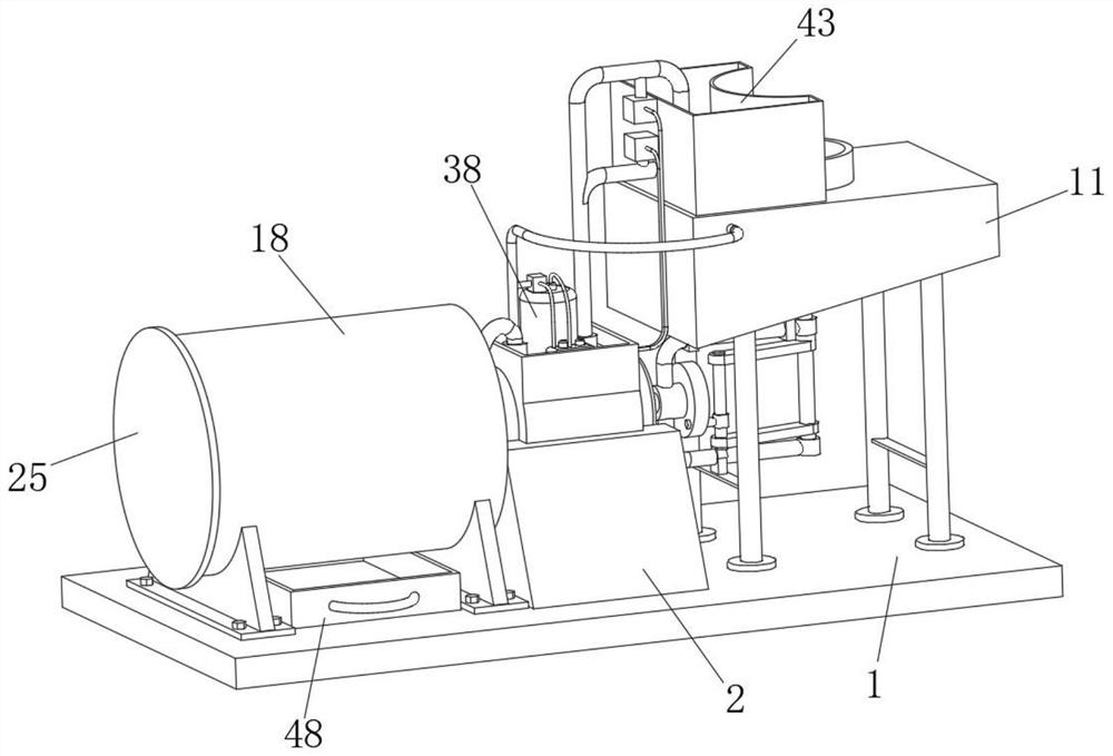
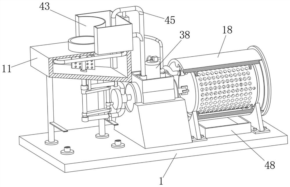
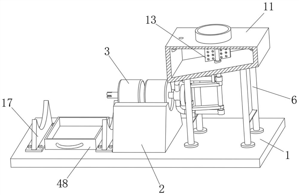
[0036] In a typical implementation of the present application, such as Figure 1-10 As shown, a stem cell intelligent centrifugal rapid extraction device includes a base plate 1, a base 2 is fixedly connected to the top of the base plat...
PUM
 Abstract
Description
Claims
Application Information