Roadway blasting structure and blasting method

A technology of roadway and detonating tube, which is applied in blasting, tunneling, earth-moving drilling and mining, etc., can solve the problems of small free surface space and increased risk of blast rejection, so as to increase compensation space, ensure safety, and increase blasting free surface space. Effect

Pending Publication Date: 2021-09-03
嵩县金牛有限责任公司
View PDF0 Cites 1 Cited by
  • Summary
  • Abstract
  • Description
  • Claims
  • Application Information

AI Technical Summary

Problems solved by technology

[0004] The purpose of the present invention is to provide a roadway blasting structure and blasting method to solve the technical problem existing in the prior art that the free surface space between the cut hole and the auxiliary hole is small, resulting in an increased risk of blast rejection

Method used


Image

  • Roadway blasting structure and blasting method
  • Roadway blasting structure and blasting method
  • Roadway blasting structure and blasting method

Examples


Embodiment 1

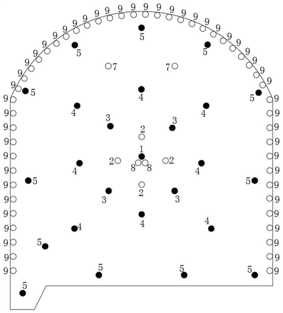
[0035] refer to figure 1 , Figure 3 to Figure 7 , this embodiment provides a roadway blasting structure, including several eye groups, the several eye groups include a first eye group consisting of a cutout center eye 1, and a second eye group composed of several cutout eyes 2 , the third eye group composed of several blasting buffer eyes 3, the fourth eye group composed of several auxiliary eyes 4, and the fifth eye group composed of several peripheral eyes 5, the first eye group and the second eye group , the third eye group, the fourth eye group and the fifth eye group are arranged sequentially from the inside to the outside and the distance between each adjacent two eye groups gradually increases from the inside to the outside. The gradually increasing distance between the eye groups is conducive to the The overall arrangement of eye positions in the roadway section is optimized to make the size of the blasting space between different eye groups more reasonable. All cut ...

Embodiment 2

[0048] refer to Figure 2 to Figure 7 , this embodiment provides a roadway blasting structure, which is mainly used in smooth surface blasting, so on the basis of the non-smooth surface blasting in embodiment 1, the roadway blasting structure also includes isolation eyes 9, and the number of isolation eyes 9 is several , all the isolation eyes 9 are distributed around the circumferential direction of the center eye 1 of the cutout and are located outside the fifth eye group, that is, the outer side of the peripheral eye 5. There is no charge structure in the isolation eyes 9, and by setting several isolation Eye 9, to achieve smooth blasting.

Embodiment 3

[0050] A blasting method based on the above roadway blasting structure, comprising the following specific steps:

[0051] S1. Select blasting roadway section;

[0052] S2. Holes are opened on the selected roadway section, and the hole types include the center hole 1 of the cutout, the hole 2 located outside the center hole 1 of the cutout, the blasting buffer hole 3 located outside the hole 2, and the hole The auxiliary eye 4 on the periphery of the buffer eye 3 and the peripheral eye 5 located on the periphery of the auxiliary eye 4 can also choose to set up space compensation eye 7 and center cut eye 8 according to actual needs. When blasting for smooth surface, it is also necessary to set up isolation eye 9 ;

[0053] S3. Put the charging structure corresponding to the cutting center hole 1, the blasting buffer hole 3, the auxiliary hole 4 and the peripheral hole 5 into the corresponding holes, and seal the outermost holes of the holes;

[0054] S4. Detonate the cutting c...


PUM


Abstract

The invention provides a roadway blasting structure and a blasting method, and relates to the technical field of roadway construction. The roadway blasting structure comprises a plurality of hole groups which comprise a first hole group consisting of a slotting central hole, a second hole group consisting of a plurality of slotting holes, a third hole group consisting of a plurality of blasting buffer holes, a fourth hole group consisting of a plurality of auxiliary holes and a fifth hole group consisting of a plurality of peripheral holes; the first hole group, the second hole group, the third hole group, the fourth hole group and the fifth hole group are sequentially arranged from inside to outside, and the distance between every two adjacent hole groups is gradually increased from inside to outside, so that the overall hole position arrangement of a section of a roadway is optimized, and a blasting space is more reasonable, and; and the blasting buffer holes are formed between the slotting holes and the auxiliary holes; and through the extrusion blasting effect of the blasting buffer holes, the blasting compensation space of the auxiliary holes is increased, so that secondary blasting is generated, a blasting free surface space of a middle area is increased, miss-fire blasting is prevented, and safety is guaranteed.

Description

technical field [0001] The invention relates to the technical field of roadway construction, in particular to a roadway blasting structure and a blasting method. Background technique [0002] Metal ores generally refer to minerals from which metal elements can be extracted after smelting, such as ferrous metal minerals: iron, manganese, chromium, vanadium, titanium, etc. are minerals used as raw materials for the iron and steel industry. Non-ferrous metal minerals include: copper, tin, zinc, nickel, cobalt, tungsten, molybdenum, mercury, etc. Precious metals include: platinum, rhodium, gold, silver, etc. Light metal minerals include: aluminum, magnesium, etc. Rare metal minerals include: lithium, beryllium, rare earth, etc. Metal minerals can be divided into five types according to their material composition, properties and uses: ferrous metal minerals, non-ferrous metal minerals, precious metal minerals, dispersed element minerals, and semi-metallic minerals. The scale ...

Claims


Application Information

Patent Timeline
IPC IPC(8): F42D1/00F42D3/04E21D9/00
CPCF42D1/00F42D3/04E21D9/006
Inventor 杨洛飞段建民王改超闫亚军赵金来张华涛
Owner 嵩县金牛有限责任公司
Why Eureka
Try Eureka