Electrostatic discharge immunity testing device
A test device and electrostatic discharge technology, which is applied in the direction of measuring device, measuring device casing, measuring electricity, etc., can solve the problems such as difficult adjustment of the position and angle of the control arm and the gun head, the inability to achieve the flexibility of the personnel's arm, and the hidden danger of electrostatic guns. , to achieve the effect of saving time, high matching degree and high safety of use
- Summary
- Abstract
- Description
- Claims
- Application Information
AI Technical Summary
Problems solved by technology
Method used
Image
Examples
Embodiment 1
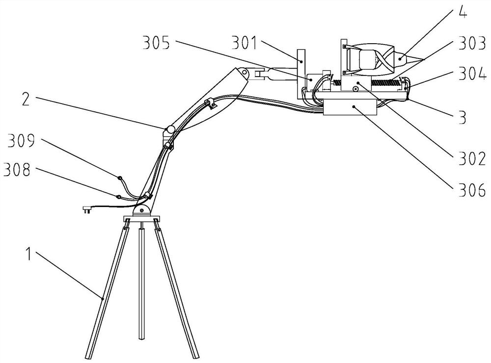
[0030] Such as figure 1 An electrostatic discharge immunity test device shown includes a frame 1, a mechanical arm assembly 2, a feed assembly 3, and an electrostatic gun 4. One end of the mechanical arm assembly 2 is hinged to the top of the frame 1 by a vertical shaft rotation, and the mechanical The other end of the arm assembly 2 is fixedly connected to the feeding assembly 3 , and the electrostatic gun 4 is arranged on the feeding assembly 3 .
[0031] The feed assembly 3 includes a feed base 301 and a feed table 302, a ball screw 303, a screw support block 304, a motor 305 and a control box 306 arranged on the feed base 301, and the feed base 301 is fixedly connected to the mechanical arm assembly 2. The feed table 302 is set on the ball screw 303, the output end of the motor 305 is connected to the ball screw 303, the two ends of the ball screw 303 are erected on the screw support block 304, and the screw support block 304 is fixed on the feed table On the surface of 3...
Embodiment 2
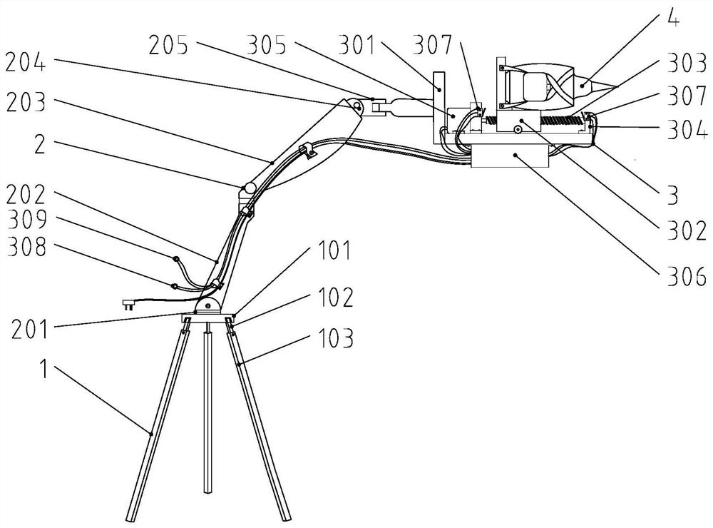
[0036] Such as figure 2An electrostatic discharge immunity test device shown includes a frame 1, a mechanical arm assembly 2, a feed assembly 3, and an electrostatic gun 4. One end of the mechanical arm assembly 2 is hinged to the top of the frame 1 by a vertical shaft rotation, and the mechanical The other end of the arm assembly 2 is fixedly connected to the feeding assembly 3 , and the electrostatic gun 4 is arranged on the feeding assembly 3 .
[0037] The frame 1 includes a mounting platform 101, three support rods 102 and three sleeve rods 103, the three support rods 102 are evenly distributed and hinged at the bottom of the installation platform 101, and the bottom end of each support rod 102 is sleeved in a sleeve rod 103 . The support rod 102 can be unfolded and folded conveniently, which is convenient for moving and arranging the whole device, and the sleeve rod 103 can slide along the support rod 102, which is convenient for adjusting the height of the installatio...
Embodiment 3
[0053] An electrostatic discharge immunity testing device, the technical solution is the same as that of embodiment 2, the difference is that:
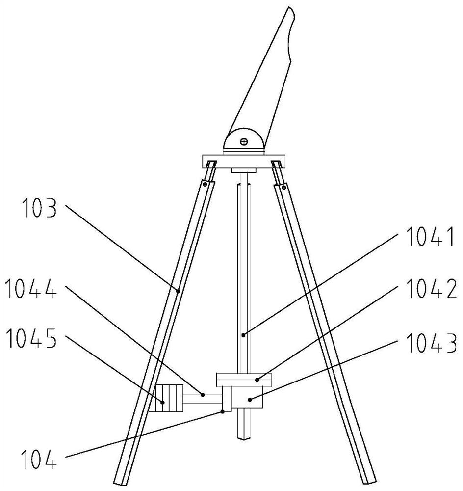
[0054] Such as image 3 As shown, the frame 1 is provided with a center of gravity adjustment part 104, and the center of gravity adjustment part 104 includes a center rod 1041, an adjustment platform 1042, an adjustment motor 1043, a connecting rod 1044 and a weight 1045, and one end of the center rod 1041 is vertically fixed to the bottom of the frame 1 , the adjustment table 1042 is rotatably hinged to the other end of the central rod 1041 by a vertical axis of rotation. The adjustment motor 1043 is a lead screw stepper motor, and the adjustment motor 1043 is located at the bottom of the adjustment table 1042. The output end of the adjustment motor 1043 is connected to the weight through the connecting rod 1044, and the adjustment motor 1043 is electrically connected with the control box 306.
[0055] The center-of-gravity adjustm...
PUM
 Abstract
Description
Claims
Application Information
 - R&D
- Intellectual Property
- Life Sciences
- Materials
- Tech Scout
- Unparalleled Data Quality
- Higher Quality Content
- 60% Fewer Hallucinations
Browse by: Latest US Patents, China's latest patents, Technical Efficacy Thesaurus, Application Domain, Technology Topic, Popular Technical Reports.
© 2025 PatSnap. All rights reserved.Legal|Privacy policy|Modern Slavery Act Transparency Statement|Sitemap|About US| Contact US: help@patsnap.com


