Front pattern structure of solar cell suitable for step-by-step printing and solar cell

A solar cell, pattern structure technology, applied in circuits, photovoltaic power generation, electrical components, etc., can solve the problems of electrically connecting main grid lines and sub grid lines, weakening current transmission capacity, and increasing contact resistance, etc. Increased current transmission path, improved current collection and transmission, small contact resistance effect

Pending Publication Date: 2021-09-03
HANWHA SOLARONE QIDONG
View PDF0 Cites 2 Cited by
  • Summary
  • Abstract
  • Description
  • Claims
  • Application Information

AI Technical Summary

Problems solved by technology

[0005] However, in the front pattern structure of the existing solar cells, on the one hand, since the printed part of the main grid uses non-burn-through front silver paste, especially the U-shaped hollow part of the main grid, which is printed integrally with the main grid, Offset is easy to occur, and because the use of non-burn-through front silver paste cannot form a good Ag-Si alloy layer with the silicon substrate, the contact resistance becomes larger and the current transmission capability becomes weaker, resulting in blackening under EL detection ; On the other hand, in the front pattern structure of the existing solar cells, although there has been a tapered connection grid at the junction of the main grid and the auxiliary grid to improve the electrical connection between the main grid line and the auxiliary grid line, it is guaranteed Current transmission, but in some cases where the printing accuracy is not enough or the equipment is old, it is still possible to electrically connect the main grid line and the auxiliary grid line only by adding a tapered connection grid

Method used


Image

  • Front pattern structure of solar cell suitable for step-by-step printing and solar cell
  • Front pattern structure of solar cell suitable for step-by-step printing and solar cell
  • Front pattern structure of solar cell suitable for step-by-step printing and solar cell

Examples


Embodiment Construction

[0036] In order to enable those skilled in the art to better understand the technical solutions of the present invention, the technical solutions in the embodiments of the present invention will be clearly and completely described below in conjunction with the drawings in the embodiments of the present invention. Obviously, the described implementation Examples are only some of the embodiments of the present invention, not all of them. Based on the embodiments of the present invention, all other embodiments obtained by persons of ordinary skill in the art without making creative efforts shall fall within the protection scope of the present invention.

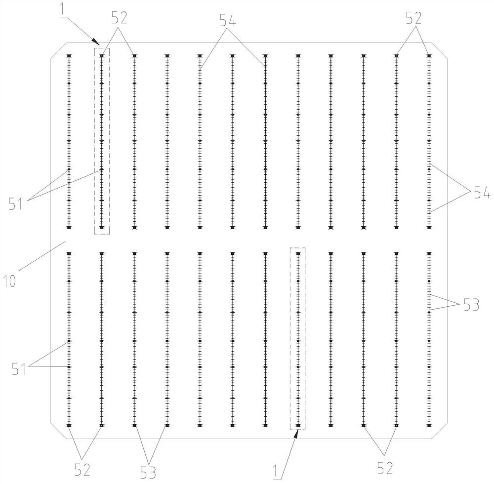
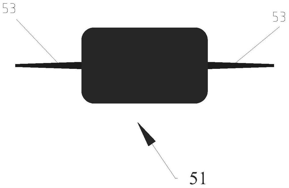
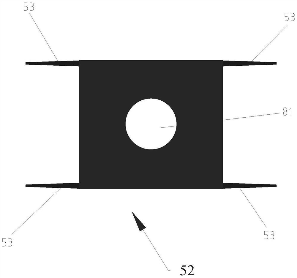
[0037] In the solar battery sheet in the present embodiment, the front graphic structure on its silicon chip 10 is by such as Figure 1-3 first printed graphics as shown and as Figure 4-7 The second printing pattern shown is formed after printing in steps.

[0038] Specifically, such as Figure 1-3 As shown, the first printi...


PUM


Abstract

The invention discloses a front pattern structure of a solar cell suitable for step-by-step printing. The front pattern structure is designed on the front side of the solar cell; the front pattern structure comprises a first printing pattern and a second printing pattern; the first printing pattern comprises a plurality of main grid lines arranged in parallel; each main grid line comprises end welding pad points located at the end of the main grid line, internal welding pad points distributed between the two end welding pad points at intervals, connecting lines connected between the end welding pad points and the internal welding pad points or between the two internal welding pad points, and first connecting grids arranged on the welding pad points and the connecting lines, the extension direction of the first connecting grids is perpendicular to the extension direction of the connecting lines; the second printing pattern comprises a hollow part corresponding to the end welding pad points and a plurality of parallel auxiliary grid lines; and the first connecting grids are used for connecting the main grid lines and the auxiliary grid lines.

Description

technical field [0001] The invention belongs to the technical field of photovoltaic modules, and in particular relates to a step-by-step printed front pattern structure of a solar cell and a solar cell including the front pattern structure. Background technique [0002] Solar photovoltaic power generation, due to its cleanliness, safety, convenience and high efficiency, has become an industry that is widely concerned and focused on development all over the world. With the continuous innovation of technology, the conversion efficiency of solar cells is also increasing rapidly, so cost reduction and efficiency increase have become the top priority of solar energy companies. [0003] The existing printing methods of solar cells can be divided into single printing, step printing and double printing. Compared with traditional single printing, step printing has the advantages of reducing unit consumption cost, improving conversion rate, and enhancing front electrode pulling force,...

Claims


Application Information

Patent Timeline
Patent Type & Authority Applications(China)
IPC IPC(8): H01L31/05H01L31/042H01L31/18
CPCH01L31/0504H01L31/0508H01L31/0512H01L31/042H01L31/1876Y02P70/50Y02E10/50
Inventor 张薛丹费存勇赵福祥
Owner HANWHA SOLARONE QIDONG
Why Eureka
Try Eureka