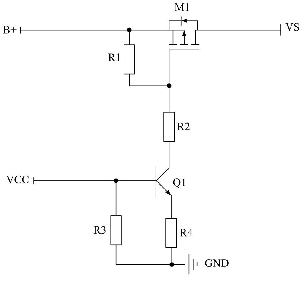
PMOS (P-channel Metal Oxide Semiconductor) tube driving circuit
A driving circuit and driving voltage technology, which is applied in the direction of electrical components, electronic switches, pulse technology, etc., can solve the problems of increasing loop power consumption, MOS tube switching function failure, and affecting MOSFET switching performance, etc., to achieve simple circuit structure and enhanced functions The effect of stability
- Summary
- Abstract
- Description
- Claims
- Application Information
AI Technical Summary
Problems solved by technology
Method used
Image

Examples
Embodiment Construction
[0028] Various exemplary embodiments of the present invention will now be described in detail with reference to the accompanying drawings. It should be noted that the relative arrangement, digital expression, and numerical value of the components and steps set forth in these embodiments are not intended to limit the scope of the present invention unless otherwise specified.
[0029] At the same time, it should be understood that in order to facilitate the description, the dimensions of the respective portions shown in the figures are not drawn in accordance with the actual ratio relationship.
[0030] The description of at least one exemplary embodiment is merely illustrative, and it is not necessary to use any limitation of the invention and its application or use.
[0031] For technical, methods, and equipment known to those of ordinary skill in the art may not be discussed in detail, in appropriate, the techniques, methods, and equipment should be considered part of the specifi...
PUM
 Abstract
Description
Claims
Application Information