A Machining Error Compensation Method for Complicated Thin-walled Structures

A technology of thin-walled structure and compensation method, applied in measuring devices, instruments, etc., can solve the problems of excessive wall thickness and low machining accuracy.

Active Publication Date: 2018-04-06
SHANGHAI SPACE PRECISION MACHINERY RES INST
View PDF0 Cites 0 Cited by
  • Summary
  • Abstract
  • Description
  • Claims
  • Application Information

AI Technical Summary

Problems solved by technology

The invention solves the problems of low processing precision and excessive wall thickness of existi

Method used


Image

  • A Machining Error Compensation Method for Complicated Thin-walled Structures
  • A Machining Error Compensation Method for Complicated Thin-walled Structures
  • A Machining Error Compensation Method for Complicated Thin-walled Structures

Examples


Embodiment Construction

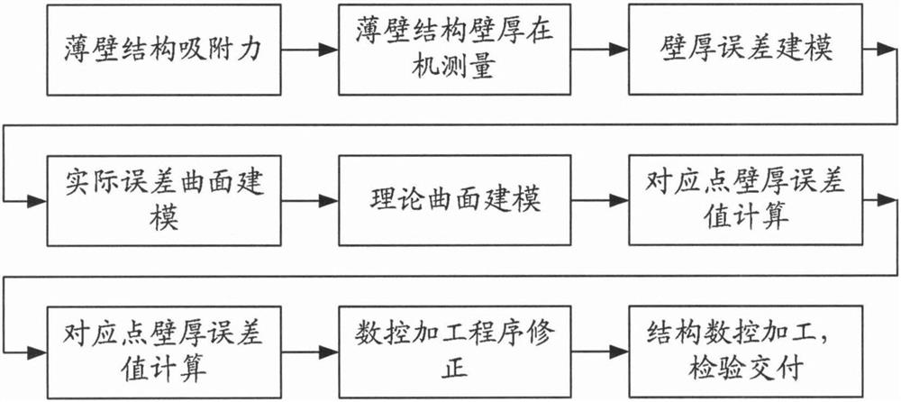
[0022] Taking the processing of thin-walled parts as an example below, the present invention will be further described in detail in conjunction with the accompanying drawings and examples.

[0023] Step 1: The negative pressure obtained by the vacuum pump is generally 0.07MPa, which can be multiplied by the surface area of ​​the part to obtain the adsorption force, and multiplied by the static friction coefficient to obtain the static friction force.

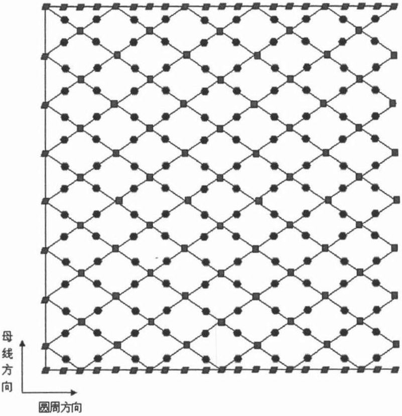
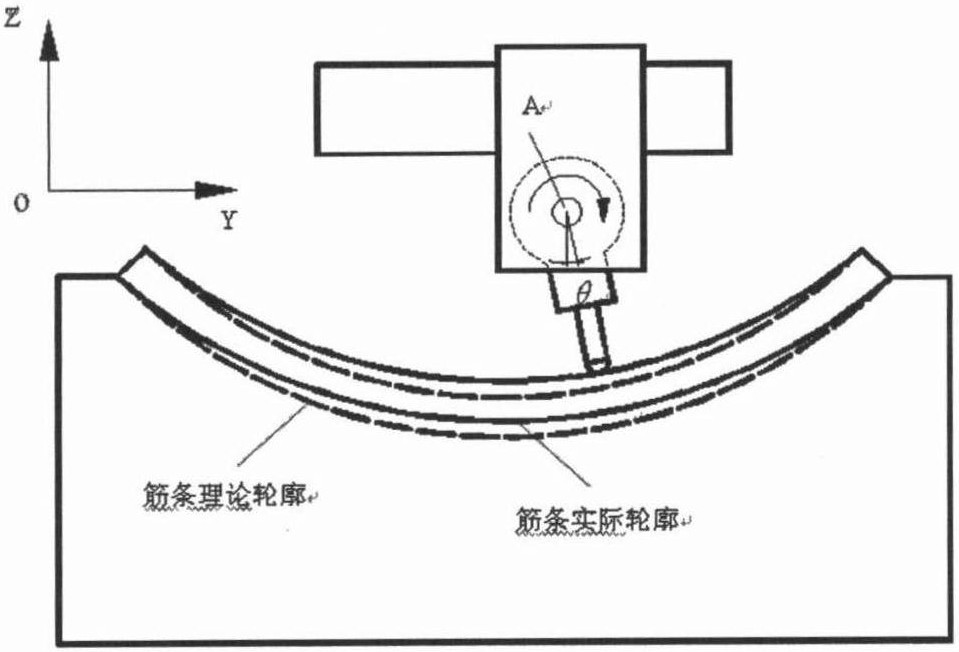
[0024] Step 2, measuring point planning according to figure 2 with image 3 When measuring, follow the direction of the generatrix first and then the direction of the circumference. The measurement points on the same bus line are one group during measurement, and the measurement result should be the contour deviation of each group of corresponding points planned, so the radial error Δδ of this position can be calculated, and the error value Δδ can be theoretically considered as the workpiece in The positioning error at this p...


PUM


Abstract

The invention discloses a processing error compensation method for a complex thin-walled structure, which comprises the following steps: (1) Firstly, the adsorption force of the thin-walled structure is obtained based on theoretical calculations to realize high-precision clamping. (2) Plan the measurement points and use the on-machine measurement software to measure the wall thickness. (3) Carry out wall thickness error modeling and calculate the thickness error value. (4) Establish the actual error surface model based on the error value and inverse technique. (5) Establish the theoretical surface model of the thin-walled structure. (6) Based on the theoretical surface model and the actual error surface model, calculate the wall thickness error value of the corresponding point. (7) Research on NC program correction algorithm and generate new NC machining program after error compensation. (8) Structural CNC machining, product inspection and delivery. The invention solves the problems of low processing precision and excessive wall thickness of existing complex thin-walled structures, and achieves beneficial effects such as improving product quality and reducing processing costs.

Description

technical field [0001] The invention relates to a method for compensating processing errors of complex thin-walled structures. Background technique [0002] The complex thin-walled structure involved in the patent of the present invention is the most typical representative of large-scale thin-walled structural parts in aerospace. It is a key part for load bearing and assembly support, and it bears huge pressure during flight. The thin-walled parts are generally designed with a grid structure, which also brings difficulties in manufacturing. At present, the method of mechanical milling is generally used in China for processing, which is difficult to guarantee the dimensional processing accuracy. Subsequent supplementary processing and manual fitter repair are required, which often leads to parts The weight is out of tolerance. [0003] In view of the above status quo, it is necessary to study a new high-efficiency processing method to solve the problem of excessive tolerance...

Claims


Application Information

Patent Timeline
IPC IPC(8): G01B21/00
Inventor 成群林穆英娟杨学勤徐爱杰唐建平李寿涛刘普林宋健
Owner SHANGHAI SPACE PRECISION MACHINERY RES INST
Why Eureka
Try Eureka