
High-precision stamping equipment

A kind of stamping equipment and high-precision technology, applied in mechanical equipment, metal processing equipment, fluid pressure actuating devices, etc., can solve the problems of affecting stamping accuracy, slow stamping forming, insufficient stamping, etc., to improve accuracy, prevent The effect of moving and preventing lag

Inactive Publication Date: 2021-09-07
广州拓康装饰材料有限公司
View PDF0 Cites 2 Cited by
  • Summary
  • Abstract
  • Description
  • Claims
  • Application Information

AI Technical Summary

Problems solved by technology

[0003] However, the existing heat-dissipating stamping parts formed by cold stamping are slow in stamping and forming, and only a single heat-dissipating stamping part can be impacted at a time. It is impossible to easily adjust the next stamping pressure according to the forming situation of the previous heat-dissipating stamping part. Many existing heat dissipation stamping parts reserve multiple shape columns on the mold, which will make the cold stamping work face a lot of resistance, resulting in greater wear and tear, and prone to insufficient stamping, and long-term use , will cause impurities in the internal hydraulic oil, resulting in stuck phenomenon, affecting the stamping accuracy

Method used


Image

  • High-precision stamping equipment
  • High-precision stamping equipment
  • High-precision stamping equipment

Examples


Embodiment Construction

[0022] The present invention is described in further detail now in conjunction with accompanying drawing. These drawings are all simplified schematic diagrams, which only illustrate the basic structure of the present invention in a schematic manner, so they only show the configurations related to the present invention.

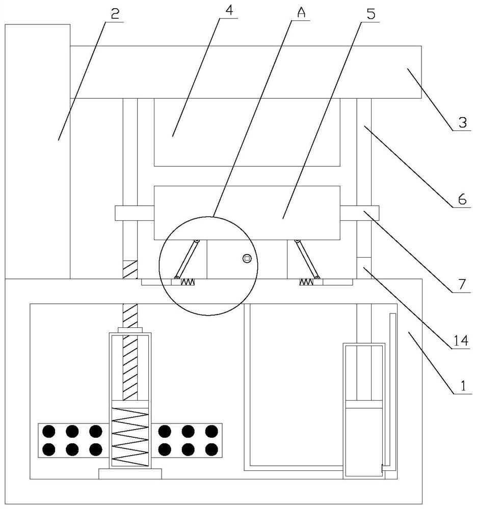
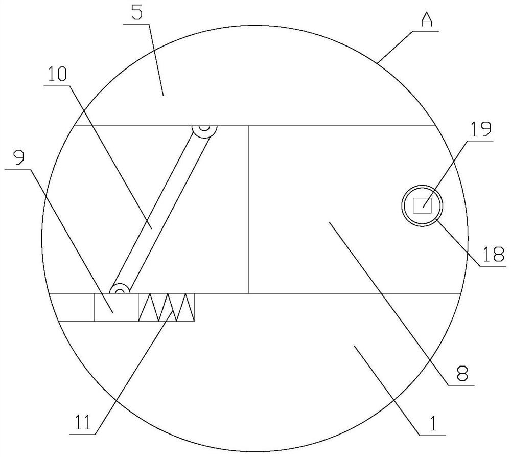
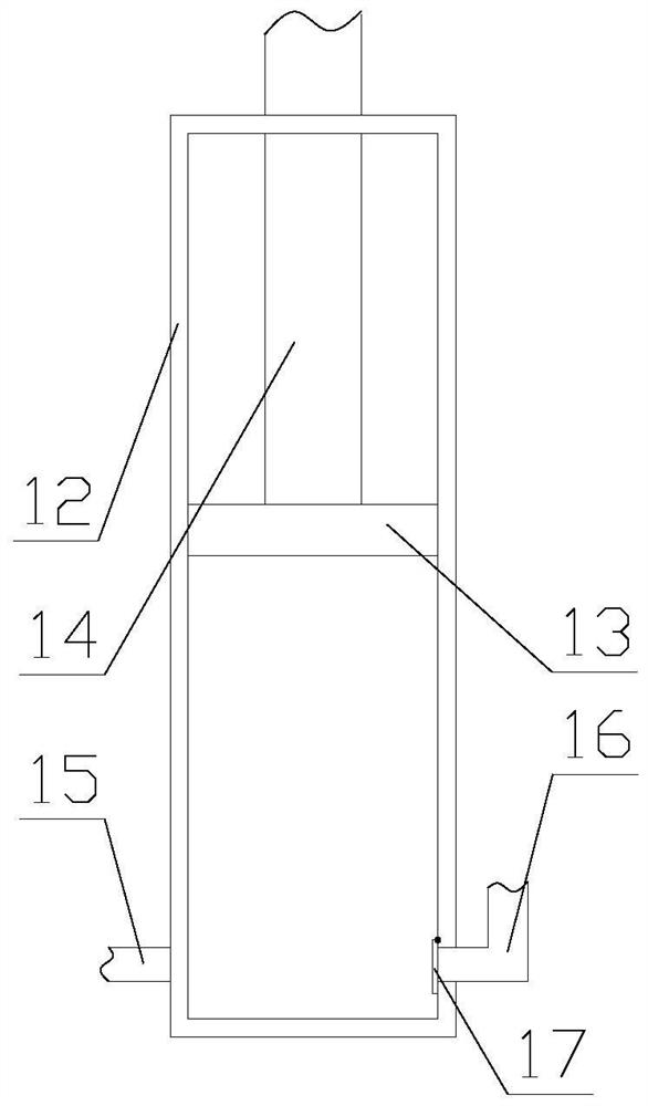
[0023] Such as Figure 1-3 As shown, a high-precision stamping equipment includes a base 1, a drive box 2, a horizontal plate 3, a stamping mechanism, a filter mechanism and a recovery mechanism, the base 1 is horizontally arranged, and the horizontal plate 3 is horizontally arranged on the base 1 Above, the drive box 2 is arranged on the base 1, the drive box 2 is provided with a drive device, one end of the horizontal plate 3 is connected to the drive device through the drive box 2, and the stamping mechanism is arranged on the horizontal plate 3 Between and the base 1, the filter mechanism is set in the base 1, and the recovery mechanism is set on the base...


PUM


Abstract

The invention relates to high-precision stamping equipment. The high-precision stamping equipment comprises a base, a driving box, a transverse plate, a stamping mechanism, a filtering mechanism and a return mechanism, wherein the stamping mechanism comprises an upper die, a lower die and a limiting assembly, the return mechanism comprises a return assembly and a buffering assembly, the filtering mechanism comprises a stirring assembly and a filtering assembly, the stirring assembly is arranged at the bottom end inside the base, the filtering assembly is arranged on the stirring assembly, and the filtering assembly is connected to the stirring assembly. According to the high-precision stamping equipment, elastic supporting of the lower die is achieved through the return mechanism, meanwhile, vibration reduction is achieved during stamping, the precision is improved during stamping, hydraulic oil is filtered through the filtering mechanism, the phenomenon of blockage is prevented, the stability is improved during the stamping, meanwhile, the hydraulic oil is stirred through a rotating plate, the flowing speed of the hydraulic oil is increased, the heat dissipation effect is improved, linkage of multiple mechanisms is achieved through the same driving source, and the use practicability is improved.

Description

technical field [0001] In particular, the invention relates to a stamping device with high precision. Background technique [0002] Cold stamping is a pressure processing method that uses a stamping die to apply pressure to a sheet or hot material on a press at room temperature to cause plastic deformation or separation to obtain parts of the desired shape and size. In cold stamping processing , cold stamping die is the technological equipment used in stamping processing. Without advanced cold stamping die, advanced stamping technology cannot be realized. Stamping equipment, molds and process conditions are the three elements of stamping processing. Because stamping forming processing must have corresponding molds, The mold is a technology-intensive product, and its manufacture is a single-piece small-batch production. It has the characteristics of difficult processing, high precision, high technical requirements, and high production costs. The advantages can be fully refle...

Claims


Application Information

Patent Timeline
Patent Type & Authority Applications(China)
IPC IPC(8): B21D22/02B21D37/10B21D37/14B21D37/16F15B21/041F15B21/042F15B21/047F16F15/023F16F15/04F16F15/06
CPCB21D22/02B21D37/10B21D37/14B21D37/16F16F15/0232F16F15/046F16F15/06F15B21/041F15B21/047F15B21/042F16F2222/126F16F2238/026
Inventor 虞伟明
Owner 广州拓康装饰材料有限公司
Learn More