Scissor foot precise assembling system

A technology for assembling system and scissors feet, which is applied in the field of scissors legs, can solve the problems of low efficiency of scissors legs and inability to meet the needs of actual production, etc.

Active Publication Date: 2021-09-07
苏州亿源精密模具有限公司
View PDF6 Cites 0 Cited by
  • Summary
  • Abstract
  • Description
  • Claims
  • Application Information

AI Technical Summary

Problems solved by technology

[0005] In view of the above-mentioned related technologies, the inventor believes that the efficiency of manual assembly of scissor legs is low, and five operators can only assemble 20,000-30,000 pieces a day, which cannot meet the actual production requirements. needs

Method used


Image

  • Scissor foot precise assembling system
  • Scissor foot precise assembling system
  • Scissor foot precise assembling system

Examples


Embodiment 1

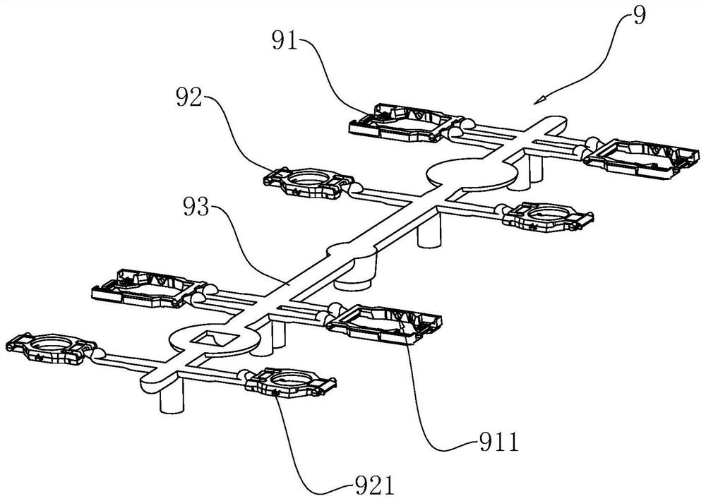
[0060] The embodiment of the present application discloses a precise assembly system of scissor feet, which is used to cut off the outer frame 91 and inner frame 92 on the batching unit 9 from the connecting rod 93 , and snap the inner frame 92 into the outer frame 91 . refer to figure 1 , The batching unit 9 includes a connecting rod 93 and an outer frame 91 and an inner frame 92 connected thereto. In this embodiment, one connecting rod 93 is provided, and four outer frames 91 and inner frames 92 are provided. The outer frames 91 are symmetrically connected in pairs on both sides of the connecting rod 93, and the inner frames 92 are symmetrically connected in pairs on both sides of the connecting rod 93; and the outer frames 91 and inner frames 92 on the same side of the connecting rod 93 are arranged alternately . At the same time, shaft grooves 911 are provided on opposite sides of the inner ring of the outer frame 91 , and correspondingly, rotating shafts 921 matching th...

Embodiment 2

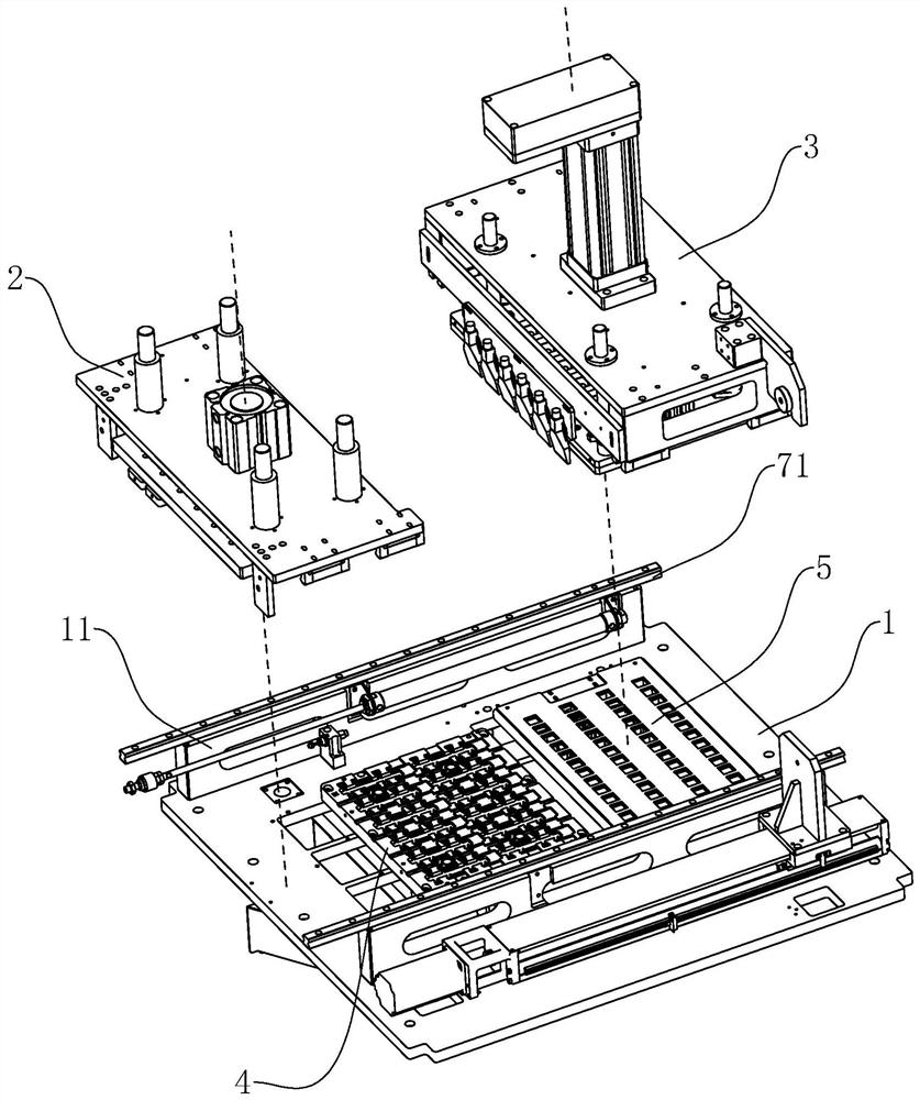
[0096] The embodiment of the present application discloses a precise assembly system for scissor feet. This embodiment is basically the same as Embodiment 1, the difference is that, with reference to Figure 13, this scissor foot precision assembly system is not provided with cylinder 62 but replaces with screw mandrel 64. Specifically, two screw mandrels 64 are horizontally arranged on the workbench 1, and the two screw mandrels 64 are symmetrically arranged on both sides of the cutting assembly 2, and are respectively located inside the corresponding slide rails 71; extending in the length direction. One end of each screw mandrel 64 is connected to the motor 65 fixed on the corresponding bracket 11 and positioned at the receiving plate 5 , and the other end is screwed to the second connection block 29 installed on the lower surface of the first fixing plate 21 . Through the cooperative rotation of the two screw rods 64 , the first fixing plate 21 can be driven, and then th...


PUM


Abstract

The invention relates to a scissor foot precise assembling system. The scissor foot precise assembling system comprises a workbench, a bottom mold plate fixedly connected to the workbench, a cutting assembly and an assembling assembly, wherein the cutting assembly and the assembling assembly are connected to the workbench in a sliding manner and can move to the position above the bottom mold plate. The cutting assembly is provided with guide columns, and guide holes allowing the guide columns to be inserted therein are formed in the bottom mold plate. A batching unit is placed on the bottom mold plate. Outer frames are arranged in inclined bottom grooves and are arranged outside stop blocks in a sleeving manner, and inner frames are arranged in flat bottom grooves. The cutting assembly is provided with a cutter used for cutting the batching unit. The assembling assembly is provided with material taking rods used for being inserted into the inner frames and clamping the inner frames into the outer frames. According to the scissor foot precise assembling system, the inner frames and the outer frames of scissor feet can be assembled in a full-automatic manner, and the assembling efficiency is improved; and meanwhile, due to the fact that the guide columns are inserted into the guide holes, the cutting precision is improved, the size performance of the inner frames and the size performance of the outer frames are improved, and then the quality of the scissor feet after assembling is improved.

Description

technical field [0001] The present application relates to the field of scissor feet, in particular to a precise assembly system for scissor feet. Background technique [0002] Membrane keyboards can be divided into crater keyboards, columnar keyboards, and scissor keyboards according to the different key structures. Scissor keyboards are widely used in notebook computers and desktop computers due to their stable keycaps, balanced pressure and fast rebound. [0003] In the scissor keyboard, the scissor foot is its core component, which determines the quality of the scissor keyboard. The scissors foot is composed of an inner frame and an outer frame; a plurality of rotating shafts are arranged symmetrically on both sides of the outer ring of the inner frame, and shaft grooves for clamping of the rotating shafts are arranged symmetrically on both sides of the inner ring of the outer frame. The inner frame is assembled in the outer frame to form the finished scissors foot by s...

Claims


Application Information

Patent Timeline
Patent Type & Authority Applications(China)
IPC IPC(8): B23P19/02
CPCB23P19/02
Inventor 叶元革叶泽仁叶毅
Owner 苏州亿源精密模具有限公司
Why Eureka
Try Eureka