Rapid positioning and clamping device for metal cutting machining

A positioning and clamping, metal cutting technology, applied in positioning devices, metal processing equipment, metal processing mechanical parts, etc., can solve the problems of manpower and material resources, low universality of fixtures

Inactive Publication Date: 2021-09-07
ZHENGZHOU UNIVERSITY OF AERONAUTICS
View PDF0 Cites 2 Cited by
  • Summary
  • Abstract
  • Description
  • Claims
  • Application Information

AI Technical Summary

Problems solved by technology

Regardless of the metal cutting method, a positioning clamping device is required to prevent the workpiece from being displaced or vibrated during processing; Develop a specific fixture, the versatility of the fixture is small, and it will consume a lot of manpower and material resources

Method used


Image

  • Rapid positioning and clamping device for metal cutting machining
  • Rapid positioning and clamping device for metal cutting machining

Examples


Embodiment 1

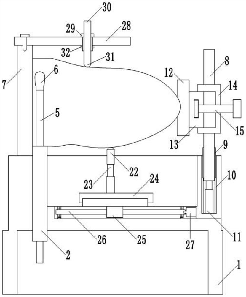
[0048] like figure 1 As shown, the embodiment of the present invention provides a quick positioning and clamping device for metal cutting, including a base 1, the upper surface of the base 1 is fixed with a clamping mechanism for clamping the front and rear sides of the part to be processed, and the upper surface of the base 1 is fixed with a clamping mechanism. A positioning mechanism for pressing the left and right sides of the part to be processed is fixed, and a support mechanism and a pressing mechanism are also fixed on the upper surface of the base 1; On the side, the lower end of the support pin 22 is connected with the telescopic end of the first electric push rod 23, the outer casing of the first electric push rod 23 is connected with the sliding part of the screw slide table 24, and the fixed part of the screw slide table 24 passes through the lateral sliding mechanism Connected with the upper surface of the base 1; the pressing mechanism includes a first plate body...

Embodiment 2

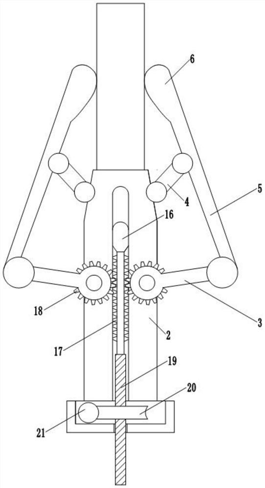
[0051] This embodiment is based on Embodiment 1, and the clamping mechanism includes a second plate body 2 longitudinally extending through a through slot on the left side of the base 1 , and two clamping units are symmetrically hinged on the left and right sides of the second plate body 2 . , each clamping unit includes: an active rocker 3, one end of which is hinged on one side of the second plate body 2; a connecting rod 5, whose lower end is hinged with the other end of the active rocker 3, and its upper end is hinged with the clamping block 6 Fixed connection; the driven rocker 4, one end is hinged to the middle of the connecting rod 5, and the other end is hinged to the second plate body 2; the length of the driven rocker 4 is less than the length of the active rocker 3; A driving mechanism is fixed on the second plate body 2, and the driving mechanism is used to drive the active rockers 3 of the two clamping units to rotate synchronously through the connecting rod 5 to d...

Embodiment 3

[0055] This embodiment is based on Embodiment 2. The positioning mechanism includes a third plate body 7 , a fourth plate body 8 , a second electric push rod 11 , a positioning block 12 and a third screw rod 15 ; the third plate body 7 is fixed on the The upper surface of the base 1 is located on the left side of the second plate body 2 at the same time; the fourth plate body 8 is located on the right side of the base 1, and a slider 9 is fixed on the left and right sides respectively. The longitudinal first chute 10 opened in the groove of the base 1 is slidably connected; the second electric push rod 11 is located below the fourth plate body 8, and its outer casing is fixed in the groove opened by the base 1 Inside, its telescopic end is longitudinally telescopic and is fixedly connected to the bottom of the fourth plate body 8 ; a slider 13 is fixed on the right side of the positioning block 12 . The horizontal second chute 14 is slidably connected; the third screw 15 is pl...


PUM


Abstract

The invention provides a rapid positioning and clamping device for metal cutting machining. The rapid positioning and clamping device for metal cutting machining comprises a base, wherein a clamping mechanism for clamping the front and rear sides of a to-be-machined part is fixed on the upper surface of the base, and a positioning mechanism for jacking the left and right sides of the to-be-machined part is further fixed on the upper surface of the base; the upper surface of the base is connected with a fixed part of a lead screw sliding table through a transverse sliding mechanism, a sliding part of the lead screw sliding table is fixedly connected with an outer shell of a first electric push rod, and the telescopic end of the first electric push rod is connected with a supporting nail and used for supporting the lower side of the to-be-machined part; a first plate body is further fixed to the base, a transverse sliding groove is formed in the first plate body, the sliding groove is in sliding connection with a sleeve, the sleeve is in threaded connection with a first screw rod, and a pressing head used for pressing the upper part of the to-be-machined part is fixed to the lower end of the first screw rod; The rapid positioning and clamping device for metal cutting machining is suitable for universal clamping of complex parts, and the clamping mechanism, the positioning mechanism, a supporting mechanism and a pressing mechanism are matched to limit the six degrees of freedom of the parts so as to guarantee stable clamping of the parts.

Description

technical field [0001] The invention belongs to the technical field of metal cutting fixtures, and particularly relates to a quick positioning and clamping device for metal cutting processing. Background technique [0002] Metal cutting is a process in which a tool is used to remove excess material from a workpiece to obtain parts that meet the requirements of shape and dimensional accuracy. Metal cutting is the most commonly used process. According to the size and shape of the machine parts on various mechanical equipment, we need to use various methods to cut them. There are many ways of metal cutting, including turning, drilling Milling, milling, grinding, boring, planing, broaching, etc. No matter what kind of metal cutting method is used, a positioning and clamping device is required to prevent the workpiece from being displaced or vibrated during processing; however, the positioning and clamping device in the prior art is generally a special fixture, which needs to be...

Claims


Application Information

Patent Timeline
Patent Type & Authority Applications(China)
IPC IPC(8): B23Q3/06
CPCB23Q3/06
Inventor 王东李征田帅石承飞王正鹤
Owner ZHENGZHOU UNIVERSITY OF AERONAUTICS
Why Eureka
Try Eureka