Method and device for monitoring tool operating condition parameters

A technology of working condition parameters and monitoring devices, applied in the direction of manufacturing tools, metal processing equipment, metal processing machinery parts, etc. Reliability is poor and other problems, to achieve the effect of optimizing metal cutting parameters, flexible structure and wide application range

Active Publication Date: 2021-11-02
西安博澜数字科技有限公司
View PDF12 Cites 0 Cited by
  • Summary
  • Abstract
  • Description
  • Claims
  • Application Information

AI Technical Summary

Problems solved by technology

[0005] The embodiment of the present application provides a method and device for monitoring tool working condition parameters, which solves the process of adjusting tool process parameters in the prior art. Most of them are optimized based on past experience or indirectly collected information analysis, and the reliability and credibility are poor. , lack of quantitative judgment, cannot flexibly match different types of tool holders, has relatively large limitations, limited application range, and has not realized the technical problem of real-time collection of tool processing parameters, so as to achieve real-time processing status by collecting tool processing parameters through relevant sensors The purpose of online detection, so as to realize the monitoring and diagnosis of the processing process, and the adjustment process of the tool process parameters has a high degree of visualization, the optimization data target is clear, the operability is strong, and different types of tool holders can be flexibly matched. The structure is flexible and the scope of application Wide, the technical effect of providing decision-making data support basis for optimizing metal cutting parameters, improving part processing quality, rational use of cutting tools and rational use of equipment capabilities

Method used


Image

  • Method and device for monitoring tool operating condition parameters
  • Method and device for monitoring tool operating condition parameters
  • Method and device for monitoring tool operating condition parameters

Examples


Embodiment 1

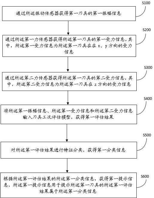
[0033] like figure 1 As shown, the embodiment of the present application provides a method for monitoring tool operating condition parameters, wherein the method includes:

[0034] Step S100: Obtain the first amplitude information of the first tool through the vibration sensor;

[0035] Step S200: Obtain first force information of the first tool through the first force sensor, wherein the first force information is force information of the first tool in the x and y directions;

[0036] Step S300: Obtain second force information of the first tool through the second force sensor, wherein the second force information is force information of the first tool in the z direction;

[0037] Specifically, the vibration amplitude information of the cutter is collected by the vibration sensor, and the effect of adding the vibration sensor to collect the amplitude information is to improve the accuracy of judgment of the working condition of the cutter. The first force information of the ...

Embodiment 2

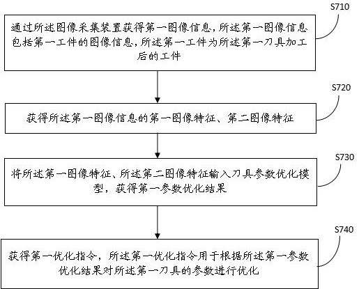
[0077] Based on the same inventive concept as the method for monitoring tool working condition parameters in the foregoing embodiments, the present invention also provides a tool working condition parameter monitoring device, such as Figure 8 As shown, the device includes:

[0078] A first obtaining unit 11, the first obtaining unit 11 is used to obtain the first amplitude information of the first tool through a vibration sensor;

[0079] The second obtaining unit 12, the second obtaining unit 12 is used to obtain the first force information of the first tool through the first force sensor, wherein the first force information is the first tool at x , Force information in the y direction;

[0080] The third obtaining unit 13, the third obtaining unit 13 is used to obtain the second force information of the first tool through the second force sensor, wherein the second force information is the first tool at z Directional force information;

[0081] A fourth obtaining unit 14...


PUM


Abstract

The invention discloses a tool working condition parameter monitoring method and device, wherein the method includes: obtaining first amplitude information of a first tool through the vibration sensor; The force information and the second force information are input into the tool condition evaluation model to obtain a first evaluation result; according to the first classification information of the first evaluation result, first prompt information is obtained, and the first prompt information The first evaluation result for prompting the first tool belongs to the first classification information. Solved the process of adjusting tool process parameters in the prior art, most of which are optimized based on past experience or indirectly collected information analysis, poor reliability and credibility, lack of quantitative judgment, and inability to flexibly match different types of tool holders, limitations Larger, the application range is limited, and the technical problem of real-time collection of tool processing parameters has not been realized.

Description

technical field [0001] The invention relates to the field of intelligent manufacturing, in particular to a method and a device for monitoring tool working condition parameters. Background technique [0002] With the development of aviation, aerospace, military, medical and other industries, higher requirements are put forward for the machining accuracy and quality stability of precision and complex parts. Since the change of cutting force is the most direct parameter to reflect the cutting state, real-time monitoring and control of cutting force plays an important role in improving the machining accuracy and surface quality of parts. [0003] However, in the process of realizing the technical solution of the invention in the embodiment of the present application, the inventor of the present application found that the above-mentioned technology has at least the following technical problems: [0004] The adjustment process of cutting tool process parameters in the existing te...

Claims


Application Information

Patent Timeline
IPC IPC(8): B23Q17/09
CPCB23Q17/0971B23Q17/0966
Inventor 周竞涛李建峰翁佩佳李红李林羲
Owner 西安博澜数字科技有限公司
Why Eureka
Try Eureka