Energy-saving and water-saving printing and dyeing device

A water-saving and treatment box technology, which is applied to the cleaning device for processing textile materials, equipment configuration for processing textile materials, textiles and papermaking, etc. It can solve the problems of pipe wall thickening, affecting the circulation of color paste, waste of color paste, etc. , to achieve the effect of promoting mixing, mixing evenly, and good stirring effect

Active Publication Date: 2021-09-07
南通欧惠纺织科技有限公司
7 Cites 0 Cited by

AI-Extracted Technical Summary

Problems solved by technology

[0003] However, when the existing printing and dyeing equipment is in use, because the color paste itself has a certain viscosity, after the color paste enters the device for storing the spinning stock solution through the pipeline, the color paste is easy to adhere to the inner wall of the pipeline, which will cause the color paste on the one hand...

Method used

Compared with embodiment 1, in the present embodiment, after air enters transition cavity 6, can at first promote piston plate 26 to move to the left, and then drive tooth bar 24 to move to the left, after piston plate 26 moves to the left to limit position, air Continue to enter the transition chamber 6, so that the air pressure in the transition chamber 6 gradually rises to the threshold of the pressure valve. When the pressure valve is opened, the gas in the transition chamber 6 is ejected. Move to the right quickly, and drive the rack 24 to move quickly to the right, so that the gear 25 and the jet pipe 9 rotate quickly. On the one hand, the fast rotation of the jet pipe 9 can further stir the color paste and the spinning stock solution, and promote the spinning stoc...

Abstract

The invention discloses an energy-saving and water-saving printing and dyeing device. The device comprises a treatment box; a partition plate is fixedly connected to the inner wall of the treatment box; a flow guide pipe is arranged on the side wall of the partition plate in a penetrating mode; the lower end of the flow guide pipe is communicated with a control box; a printing and dyeing box is fixedly connected to the bottom in the treatment box; a scraping mechanism used for scraping color paste on the inner wall of the flow guide pipe is arranged in the treatment box; the scraping mechanism comprises a rotating shaft; a plurality of rotating plates are fixedly connected to the side wall of the rotating shaft; the rotating shaft extends out of the control box and is fixedly connected with a fixing plate; a limiting rod is fixedly connected to the side wall of the fixing plate; two guide rods are fixedly connected to the inner wall of the treatment box; the side walls of the two guide rods are jointly and slidably connected with a movable plate in a sleeved mode; and the side wall of the movable plate is fixedly connected with a connecting rod. The color paste on the inner wall of the flow guide pipe can be scraped off, so that the color paste is prevented from being attached to the inner wall of the flow guide pipe for a long time to form coagulated scales, and the situation that circulation of the color paste is affected due to thickening of the pipe wall is prevented.

Application Domain

Textile treatment machine arrangementsTextile treatment cleaning apparatus

Technology Topic

DyeingStructural engineering +2

Image

  • Energy-saving and water-saving printing and dyeing device
  • Energy-saving and water-saving printing and dyeing device
  • Energy-saving and water-saving printing and dyeing device

Examples

  • Experimental program(2)

Example Embodiment

[0031] Example 1
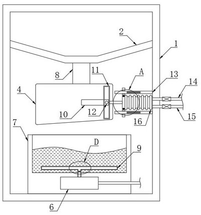
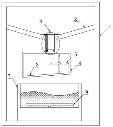
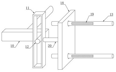
[0032] refer to Figure 1-3 , an energy-saving and water-saving printing and dyeing device, comprising a processing box 1, further, a pipeline for supplementing color paste can be arranged on the upper wall of the processing box 1, the inner wall of the processing box 1 is fixedly connected with a partition 2, and the side walls of the partition 2 There is a guide pipe 8 running through it, and further, a valve can be set on the guide pipe 8 to control the flow of the color paste on the upper end of the partition plate 2. The pulp flows into the guide pipe 8, the lower end of the guide pipe 8 is connected with a control box 4, the bottom of the control box 4 is provided with a through hole 3, and the inner bottom of the processing box 1 is fixedly connected with a printing and dyeing box 7.
[0033] The processing box 1 is provided with a scraping mechanism for scraping the color paste on the inner wall of the guide tube 8. The scraping mechanism includes a rotating shaft. The rotating plates 5 are all in a spoon-shaped structure, and the guide tube 8 is arranged directly on the leftmost rotating plate 5 to ensure that the color paste flowing out of the guide tube 8 can impact the rotating plate 5 to make the rotating plate 5 rotate. The bottom of the control box 4 is provided with a guide. The inclined surface of the through opening 3 facilitates the color paste to flow out from the through opening 3, and prevents the color paste from accumulating in the control box 4, thereby ensuring that the rotating plate 5 can rotate smoothly;
[0034] The rotating shaft extends to the outside of the control box 4 and is fixedly connected with a fixing plate 10. The side wall of the fixing plate 10 is fixedly connected to a limit rod 12. The limit rod 12 is located on the side wall of the fixing plate 10 near the right end. The inner wall of the processing box 1 is fixedly connected with two The guide rod 13, the side walls of the two guide rods 13 are slidably connected to the moving plate 18, the side wall of the moving plate 18 is fixedly connected with a connecting rod 20, one end of the connecting rod 20 is fixedly connected with the moving frame 11, and the limit rod 12 is located in the moving frame. 11, the length of the inner ring of the moving frame 11 must be greater than the diameter of the rotation track of the limit rod 12 to ensure that the limit rod 12 can rotate smoothly. A conducting coil 17 is fixed and embedded inside, and the conducting coil 17 is a non-closed coil;
[0035] refer to figure 2 and Figure 5 , the side wall of the guide tube 8 is fixedly connected with an electromagnetic ring 22, the electromagnetic ring 22 is electrically connected with the guide coil 17, the inner wall of the guide tube 8 is slidably connected with a permanent magnet ring 23, and the upper side wall of the partition plate 2 is fixedly connected with two fixed Bar 21, the two fixing bars 21 are both L-shaped structures, the permanent magnet ring 23 is slidably sleeved on the side walls of the two fixing bars 21, and further, the lower ends of the two fixing bars 21 are provided with limit rings to prevent the permanent magnet ring 23 fall.
[0036] refer to figure 1 , Figure 4 and Figure 8 The processing box 1 is provided with a mixing mechanism for promoting the mixing of color paste and spinning dope. The mixing mechanism includes a telescopic air bag 16 fixedly connected to the side wall of the moving plate 18. The right end of the telescopic air bag 16 is fixedly connected to the inner wall of the processing box 1. 16 The side wall is communicated with a one-way suction pipe 14, and the one-way suction pipe 14 and the one-way air outlet pipe 15 below are both provided with a one-way valve in the existing pipeline, and the one-way suction pipe 14 only allows The air enters into the telescopic air bag 16 from the outside, and the bottom of the printing and dyeing box 7 is provided with a transition cavity 6. The transition cavity 6 is communicated with the telescopic air bag 16 through the one-way air outlet pipe 15. The one-way air outlet pipe 15 only allows air to enter the transition chamber from the telescopic air bag 16. 6, the interior of the printing and dyeing box 7 is provided with a jet pipe 9, the jet pipe 9 is formed of a plurality of jet holes provided by the pipe body and the side wall of the pipe body, the section of the jet pipe 9 is a T-shaped structure, and the jet pipe 9 is provided with a pressure valve. , the lower end of the jet pipe 9 communicates with the transition cavity 6 .
[0037] The functional principle of the present invention can be explained by the following operation methods: when the spinning stock solution needs to be printed and dyed, the color paste is first mixed and poured into the upper end of the separator 2 in proportion, and then the valve on the guide pipe 8 is opened, and the color paste will pass through. The guide pipe 8 flows into the control box 4 , and then flows into the printing and dyeing box 7 through the through port 3 , and is mixed with the spinning dope in the printing and dyeing box 7 .
[0038]When the color paste flows out of the guide tube 8, it will impact the rotating plate 5, so that the rotating plate 5 rotates, which in turn drives the rotating shaft to rotate, so that the fixed plate 10 and the limit rod 12 rotate, and the limit rod 12 rotates to make the moving frame 11 move back and forth. , so that the moving plate 18 and the guide coil 17 move back and forth, and the guide coil 17 moves back and forth to cut the magnetic field line between the two magnetic strips 19 to generate an induced current, so that the electromagnetic ring 22 is energized to generate magnetism, and when the guide coil 17 moves to the right , the opposite poles of the electromagnetic ring 22 and the permanent magnet ring 23 are opposite poles, the permanent magnet ring 23 moves up under the action of the attractive force, and when the guide coil 17 moves to the left, the opposite magnetic poles of the electromagnetic ring 22 and the permanent magnet ring 23 have the same pole , Under the action of the repulsion force and its own gravity, the permanent magnet ring 23 will move downward, repeating the above operation, the permanent magnet ring 23 will reciprocate up and down, so as to prevent the color paste from adhering to the guide tube 8 and forming a fouling situation. , so as to prevent the occurrence of the situation that the pipe wall of the guide pipe 8 is gradually "thickened" and affects the circulation of the color paste.
[0039] When the moving plate 18 moves to the left, the outside air can also be sucked into the telescopic air bag 16, and when the moving plate 18 moves to the right, the air in the telescopic air bag 16 can be squeezed into the transition chamber 6, and the above operation is repeated, and the air continues to enter To the transition chamber 6, the air pressure in the transition chamber 6 is continuously increased. When the air pressure reaches the threshold value of the pressure valve, the pressure valve is opened, and the high-pressure gas is ejected from the jet pipe 9 at a high speed to form a large number of bubbles, which can stir the color paste and the spinning stock solution. , so as to promote the mixing of color paste and spinning dope, and improve the printing and dyeing effect of spinning dope.

Example Embodiment

[0040] Example 2
[0041] refer to Figure 6-7 , The difference between this embodiment and Embodiment 1 is that the inner wall of the transition chamber 6 is elastically connected with a piston plate 26 through a compression spring, and the piston plate 26 is sealed and slidingly connected to the inner wall of the transition chamber 6. Further, the left side of the transition chamber 6 needs to be connected to The outside is connected to ensure that the piston plate 26 can move to the left smoothly, the right side wall of the piston plate 26 is fixedly connected with the rack 24, the lower end of the jet pipe 9 extends into the transition chamber 6 and is fixedly connected with the gear 25 meshing with the rack 24, spraying The trachea 9 is rotatably connected to the bottom of the printing and dyeing box 7 through a rotary joint.
[0042] Compared with Embodiment 1, in this embodiment, after the air enters the transition chamber 6, it will first push the piston plate 26 to move to the left, and then drive the rack 24 to move to the left. After the piston plate 26 moves to the limit position, the air continues to enter the transition. When the pressure valve is opened, the gas in the transition chamber 6 is ejected, and at the same time, the piston plate 26 will also rapidly move to the right under the elastic force of the compression spring. move, and drive the rack 24 to move to the right quickly, so that the gear 25 and the jet tube 9 rotate rapidly. On the one hand, the rapid rotation of the jet tube 9 can further stir the color paste and the spinning dope, and promote the mixing of the spinning dope and the color paste. , to improve the printing and dyeing effect. On the other hand, the rapid rotation of the air jet pipe 9 can make the air bubble cover a wider range, so that the mixed liquid in the printing and dyeing box 7 can be mixed more comprehensively.

PUM

no PUM

Description & Claims & Application Information

We can also present the details of the Description, Claims and Application information to help users get a comprehensive understanding of the technical details of the patent, such as background art, summary of invention, brief description of drawings, description of embodiments, and other original content. On the other hand, users can also determine the specific scope of protection of the technology through the list of claims; as well as understand the changes in the life cycle of the technology with the presentation of the patent timeline. Login to view more.

Similar technology patents

Mining machinery coal sample mixing machine

PendingCN113029741Apromote mixingshorten the time
Owner:徐立堂

Catalytic combustion reactor

PendingCN112032744Apromote mixingfully vaporized
Owner:广东醇氢新能源研究院有限公司

Asphalt emulsifying equipment

PendingCN114713057Apromote mixingquality improvement
Owner:安徽川微建筑工程有限公司

Chlorine-containing plastic pyrolysis oil production system based on premelting treatment

ActiveCN113025368Apromote mixingenhanced interaction
Owner:CHONGQING UNIVERSITY OF SCIENCE AND TECHNOLOGY

Classification and recommendation of technical efficacy words

  • promote mixing

Low NOx fuel gas burner based on venturi tubes

InactiveCN103486572AReduce NOx formationpromote mixing
Owner:CHANGSHA UNIVERSITY OF SCIENCE AND TECHNOLOGY

A double-nozzle flat-plate micro-combustion chamber based on hydrocarbon fuel

InactiveCN102278741Aachieve diffusivitypromote mixing
Owner:JIANGSU UNIV

Quick uniform mixing device for gas

PendingCN107051241Apromote mixingImprove mixing efficiency
Owner:YANCHENG CIVIL MACHINERY CO LTD

Multi-crankshaft concrete mixer

ActiveCN103128855Apromote mixingImprove stirring efficiency
Owner:润桐(苏州)技术服务有限公司

Device and method for the production of a powder-air mixture

InactiveUS7607451B2promote mixing
Owner:WEITMANN & KONRAD
Why Eureka
Try Eureka