
Layered rock-soil pressing and pulling combined anchor rod and using method thereof

An anchor rod, geotechnical technology, applied in construction, sheet pile wall, foundation structure engineering and other directions, can solve the problems of different shear strength, damage of anchoring section, etc.

Pending Publication Date: 2021-09-07
CHINA CONSTR FOURTH ENG DIV
View PDF0 Cites 0 Cited by
  • Summary
  • Abstract
  • Description
  • Claims
  • Application Information

AI Technical Summary

Problems solved by technology

[0005] The purpose of the present invention is to provide a layered rock-soil compression-tension composite bolt, which can solve the problem of failure of the anchorage section caused by the different shear strength of the rock-soil body when the existing compression-tension composite bolt is applied to the layered rock-soil body Phenomenon

Method used


Image

  • Layered rock-soil pressing and pulling combined anchor rod and using method thereof
  • Layered rock-soil pressing and pulling combined anchor rod and using method thereof

Examples


Embodiment 1

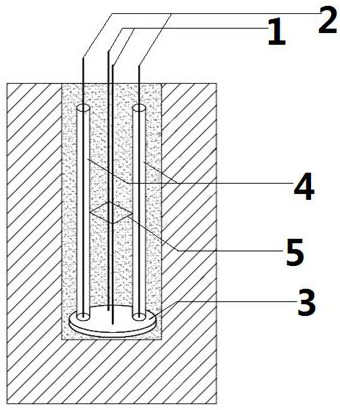
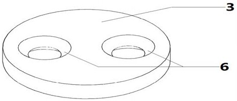
[0031] Embodiment 1: There are two pressure anchor bars 2 and two tension anchor bars 1, which are evenly distributed with the center of the bearing plate 3 as the center of the circle. The anchor bars of the same kind are arranged opposite to each other, and the positioning bracket 5 is a square.

Embodiment 2

[0032] Embodiment 2: Pressure anchor bar 2, tension anchor bar 1, one anchor bar is one, the other anchor bar is two, only one anchor bar is set in the center of the bearing plate, and the other anchor bar is used to carry The central points of the plates 3 are distributed symmetrically, and the positioning bracket 5 is in the shape of a line.

[0033] Through the different setting methods of the tension anchor bar 1 and the pressure anchor bar 2, it can adapt to the conditions of different rock and soil bodies and ensure the best anchoring effect.

[0034] In order to prevent the grout from entering the casing 4 and bonding with the pressure anchor bars 2, the connection between the casing 4 and the bearing plate 3 can be sealed with epoxy resin.

[0035] The method for using the above-mentioned layered rock-soil compression-tension composite anchor comprises the following steps:

[0036] 1) Measure the rock and soil layer around the anchorage section, and determine the numb...

Embodiment 3

[0041] When the rock-soil layer does not appear delamination with depth, there are two tension anchor bars 1 and two pressure anchor bars 2, and the diameters are the same.


PUM


Abstract

The invention discloses a layered rock-soil pressing and pulling combined anchor rod and a using method thereof. The layered rock-soil pressing and pulling combined anchor rod comprises tension anchor bars, pressure anchor bars, a bearing plate, sleeves and positioning supports, the tension anchor bars and the pressure anchor bars are located at the same side of the bearing plate, the tension anchor bars and the bearing plate are vertically connected in a spot welding manner, the pressure anchor bars are sleeved with the sleeves, and the pressure anchor bars, the sleeves and the bearing plate are vertically and fixedly connected; and the positioning supports are fixedly connected with the tension anchor bars and the sleeves and are evenly distributed in the length direction of the anchor bars. When the combined anchor rod is used, a rock-soil layer on the periphery of an anchoring section is measured firstly, the number and the diameter of the tension anchor bars and the pressure anchor bars are determined according to the layering and shearing strength conditions of the rock-soil layer, and the combined anchor rod is manufactured and then placed into an anchor hole for grouting. By changing the diameter and the number of the anchor bars of the pressing and pulling combined anchor rod, loads are distributed more reasonably on the premise of being evenly distributed, the uplift bearing capacity of the anti-floating anchor rod is improved, and the situation that due to stress concentration, an anchoring body is damaged, and consequently the overall structure is damaged is avoided.

Description

technical field [0001] The invention belongs to the field of geotechnical engineering construction, and in particular relates to a compression-tension composite anchor rod and a using method thereof. Background technique [0002] For the foundation pit project near the river, due to the existence of groundwater and the frequent stratification of rock and soil, its anti-floating problem has become the focus and difficulty of the construction process, so the support system used under this condition needs to have a high Pullout resistance. [0003] At present, the commonly used anchoring systems in engineering are tension anchors and pressure anchors. When the tensile anchor is stressed, the tensile force borne by the anchor bar is transmitted to the mortar through the grip force of the mortar around the anchor, and then transmitted to the stable stratum in the anchorage area through the frictional resistance of the surrounding stratum of the anchorage section. pull state. W...

Claims


Application Information

Patent Timeline
IPC IPC(8): E02D5/74
CPCE02D5/74
Inventor 夏小兵夏凯刑领张明礼吴静罗丹
Owner CHINA CONSTR FOURTH ENG DIV
Learn More