Water seal type backfire prevention mechanism

A technology of water sealing and sealing valve, applied in mechanical equipment, engine components, valve devices, etc., can solve the problems of cumbersome use, poor stability and reliability, affecting the flame temperature of combustible gas, etc., and achieve the effect of avoiding further expansion.

Active Publication Date: 2021-09-07
湖南八达人防科技股份有限公司
View PDF14 Cites 0 Cited by
  • Summary
  • Abstract
  • Description
  • Claims
  • Application Information

AI Technical Summary

Problems solved by technology

[0007] The present invention provides a water-sealed tempering prevention mechanism, which can perform water-seal action in case of accidents, but does not perform water-seal under normal conditions , Effectively ensure the dryness of the combustible gas when passing through, will not cause water-based corrosion to the sealing parts in the pipeline system, will not affect its flame temperature during combustion, and no longer need to check the water level due to the loss of water vapor The advantages of high detection and supplementation, stability and reliability solve the problem that the existing water-sealed flashback preventer requires combustible gas to penetrate the sealed water-sealed layer during use, which may cause a small amount of combustible gas to carry The water vapor enters the pipeline system or combustion equipment, causing corrosive damage to various sealing parts in the pipeline system, and greatly affects the flame temperature of the combustible gas during combustion. At the same time, due to the loss of water vapor It is also necessary to detect and replenish the water level in the valve body from time to time, which is cumbersome to use and has poor stability and reliability.

Method used


Image

  • Water seal type backfire prevention mechanism
  • Water seal type backfire prevention mechanism
  • Water seal type backfire prevention mechanism

Examples


Embodiment Construction

[0025] The following will clearly and completely describe the technical solutions in the embodiments of the present invention with reference to the accompanying drawings in the embodiments of the present invention. Obviously, the described embodiments are only some, not all, embodiments of the present invention. Based on the embodiments of the present invention, all other embodiments obtained by persons of ordinary skill in the art without making creative efforts belong to the protection scope of the present invention.

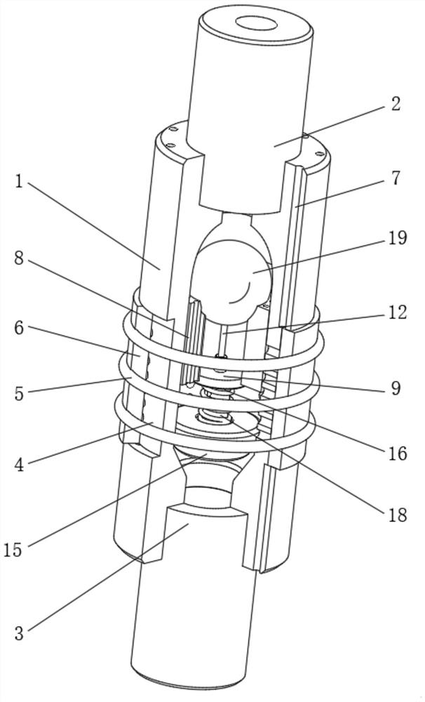
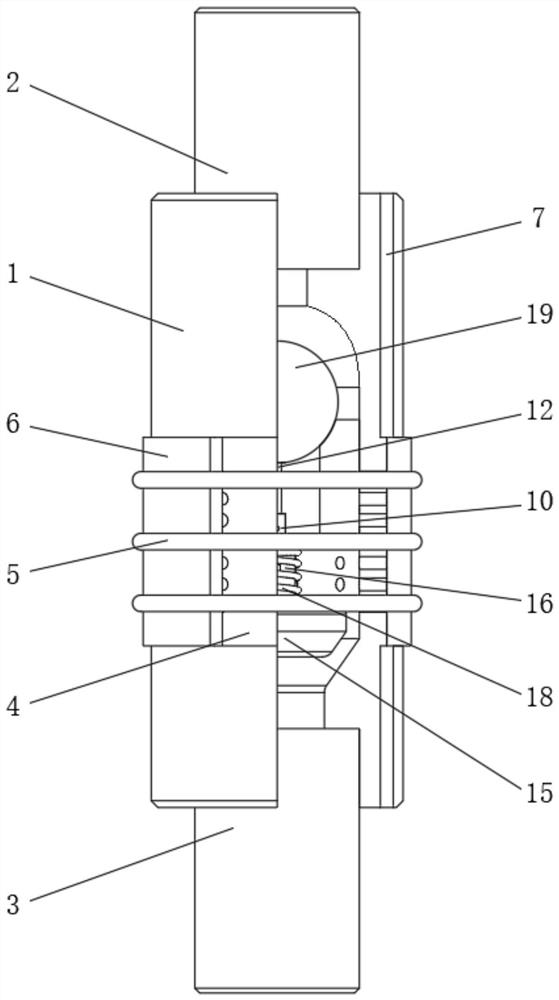
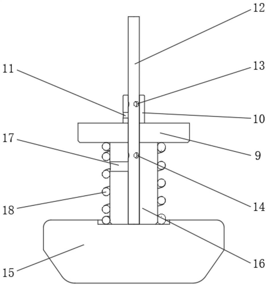
[0026] see Figure 1-3 , a water-sealed tempering prevention mechanism, including a fixed valve body 1, a set of outlet pipe mouth 2 and an air inlet pipe mouth 3 are fixedly installed on the top and bottom ends of the fixed valve body 1 respectively, and the middle part of the outer surface of the fixed valve body 1 is opened There is an annular groove 4, and the inside of the inlet pipe mouth 3 is provided with a through hole connected to its inner cavity. T...


PUM


Abstract

The invention relates to the technical field of pipeline fire retardant equipment, and discloses a water seal type backfire prevention mechanism comprising a fixed valve body, the top end and the bottom end of the fixed valve body are fixedly provided with a gas outlet pipe opening and a gas inlet pipe opening correspondingly, and an annular groove is formed in the middle of the outer surface of the fixed valve body. A through hole communicating to an inner cavity of the gas inlet pipe opening is formed in the gas inlet pipe opening, and a sealing clamping plate is fixedly clamped to the inner wall of the annular groove through an elastic rubber ring. According to the water seal type backfire prevention mechanism, due to setting of the relative position relation of a communicating groove I, a communicating groove II and a flow guide groove I and a flow guide groove II in a fixed connecting rod, a sealing valve element and the fixed connecting rod on the sealing valve element can be timely and effectively driven to move downwards, and an aqueous solution injected in an inner cavity of a fire banking plate is led into an inner cavity of the fixed valve body. Then water seal is formed in the fixed valve body, and therefore flame temperature or heat waves are prevented from impacting and penetrating through the fire banking plate and directly making contact with the sealing valve element.

Description

technical field [0001] The invention relates to the technical field of pipeline fire arresting equipment, in particular to a water-sealed backfire prevention mechanism. Background technique [0002] The water seal flame arrester is a safety protection device installed at the positive pressure end of the pipeline. When an accidental explosion occurs in the combustible gas pipeline, it can prevent the shock wave generated by the explosion from destroying the pressure system in the pipeline system. At the same time, it can block the explosion. The resulting flame conducts along the gas pipeline and produces a flashback phenomenon, which effectively avoids further expansion of the situation. [0003] Among them, the water-sealed flashback preventer is the most widely used structural form on the market. Under normal working conditions, combustible gas enters the valve body from the intake pipe, and passes through the water through the check valve at the bottom. The sealing layer...

Claims


Application Information

Patent Timeline
IPC IPC(8): F16K17/38F16K17/40
CPCF16K17/38F16K17/40
Inventor 鞠长军
Owner 湖南八达人防科技股份有限公司
Why Eureka
Try Eureka