Salt-cavern gas storage gas-liquid interface measurement method and system based on low-frequency electric signal
A technology of gas-liquid interface and measurement method, which is applied to the liquid level indicator for physical variable measurement, etc., can solve the problems that the measurement method is easily affected by the environment, measurement errors, etc., and achieves long service life, reduced replacement times, and less interference in use. Effect
- Summary
- Abstract
- Description
- Claims
- Application Information
AI Technical Summary
Problems solved by technology
Method used
Image
Examples
Embodiment 1
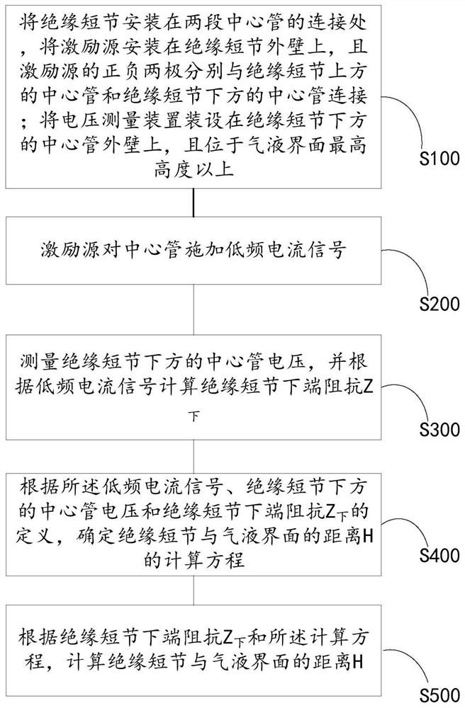
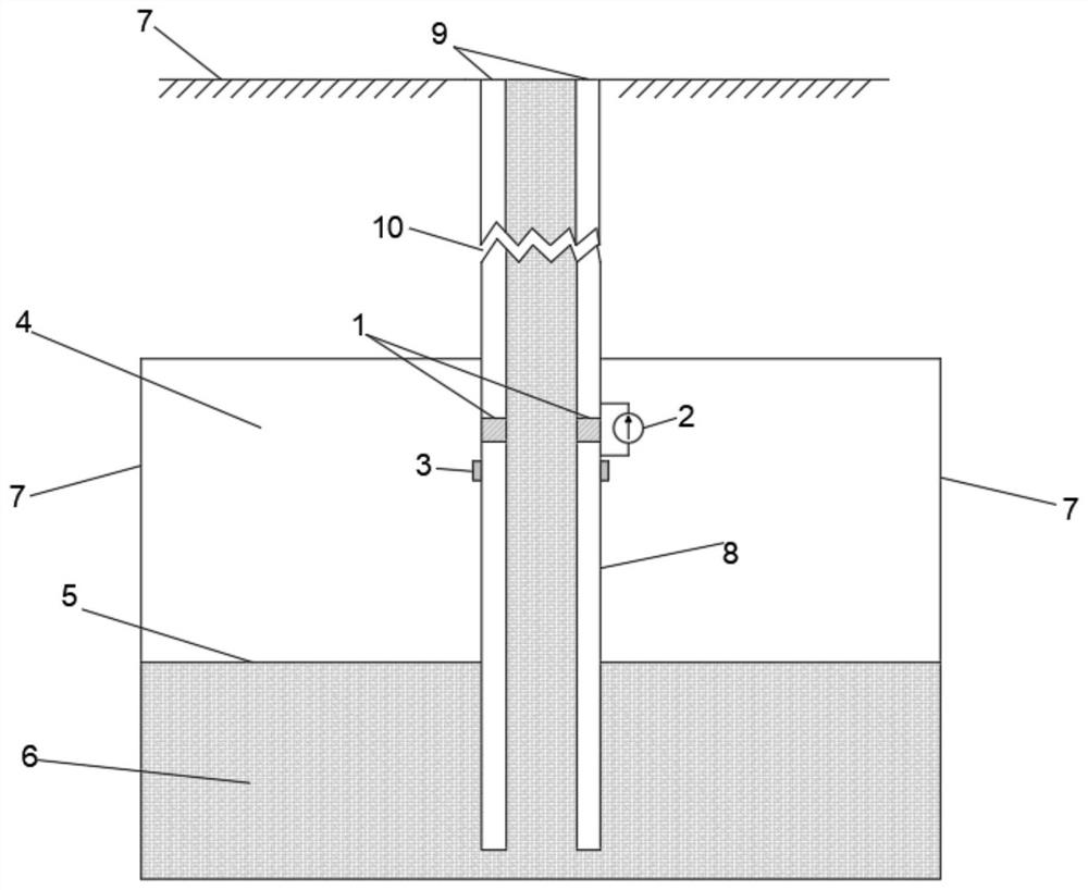
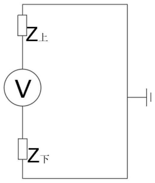
[0031] refer to figure 1 , in the first aspect of the present invention, a method for measuring the gas-liquid interface of a salt cavern gas storage based on low-frequency electrical signals is provided, including: S100. Install the insulating puppet at the junction of two sections of central pipe, and install the excitation source on the insulating On the outer wall of the pup joint, and the positive and negative poles of the excitation source are respectively connected to the outer wall of the central tube above the insulating pup joint and the outer wall of the central tube below the insulating pup joint; the voltage measuring device is installed on the outer wall of the central tube below the insulating pup joint, And it is located above the highest height of the gas-liquid interface; S200. The excitation source applies a low-frequency current signal to the central tube; S300. Measure the voltage of the central tube under the insulating pup, and calculate the impedance Z o...
Embodiment 2
[0068] The second aspect of the present invention provides a gas-liquid interface measurement system for salt cavern gas storage based on low-frequency electrical signals, including: a central pipe, an insulating pup, an excitation source, a voltage measuring device, and a computing device. The insulating pup is installed At the junction of the two sections of central pipe; the excitation source is installed on the outer wall of the insulating pup, and its positive and negative poles are respectively connected to the outer wall of the central pipe above the insulating pup and the outer wall of the central pipe below the insulating pup. The central tube applies a low-frequency current signal I; the voltage measuring device is installed on the outer wall of the central tube under the insulating sub, and is located above the highest height of the gas-liquid interface, and is used to measure the central tube voltage U under the insulating sub 下 ; The computing device is connected t...
Embodiment 3
[0075] A third aspect of the present invention provides an electronic device, including: one or more processors; a storage device for storing one or more programs, when the one or more programs are used by the one or more The processor executes, so that the one or more processors implement the method provided by the first aspect of the present invention.
[0076] Specifically, refer to Figure 7 , the electronic device 500 may include a processing device (such as a central processing unit, a graphics processing unit, etc.) 501, which may be loaded into a random access memory (RAM) 503 according to a program stored in a read-only memory (ROM) 502 or loaded from a storage device 508 Various appropriate actions and processing are performed by the programs in the program. In the RAM 503, various programs and data necessary for the operation of the electronic device 500 are also stored. The processing device 501 , ROM 502 and RAM 503 are connected to each other through a bus 504 ...
PUM
 Abstract
Description
Claims
Application Information
 - R&D
- Intellectual Property
- Life Sciences
- Materials
- Tech Scout
- Unparalleled Data Quality
- Higher Quality Content
- 60% Fewer Hallucinations
Browse by: Latest US Patents, China's latest patents, Technical Efficacy Thesaurus, Application Domain, Technology Topic, Popular Technical Reports.
© 2025 PatSnap. All rights reserved.Legal|Privacy policy|Modern Slavery Act Transparency Statement|Sitemap|About US| Contact US: help@patsnap.com


