Rapid dielectric temperature spectrum test method

A technology of dielectric thermospectrum and testing method, which is applied in the field of rapid dielectric thermospectral testing, which can solve the problems of not being able to immediately follow the temperature change of the test environment, and achieve the effect of shortening the test time

Active Publication Date: 2021-09-07
NANTONG UNIVERSITY
View PDF15 Cites 1 Cited by
  • Summary
  • Abstract
  • Description
  • Claims
  • Application Information

AI Technical Summary

Problems solved by technology

However, if the temperature of the dielectric test environment displayed during a certain dielectric test is 65°C, due to the thermal inertia (heat capacity) of the sample and the fixture holding the sample, the actual temperature of the sample cannot immediately follow the temperature of the test environment. Temperature changes, the sample temperature at this moment is not equal to 65°C, it may only be 63.3°C

Method used


Image

  • Rapid dielectric temperature spectrum test method

Examples


specific Embodiment approach 1

[0041] Specific implementation mode one: a fast dielectric temperature spectrum testing method, using the figure 1 The dielectric thermospectroscopy measurement system shown. The impedance tester 1 is connected to the dielectric test electrode 8; the variable temperature test box 3 is used to provide a variable temperature environment for the sample to be tested; the computer 4 in the measurement system is used to run the measurement system software; the display 5 is used to display operation and measurement information; the test Table 6 is used to place various equipment of the measurement system, such as impedance tester 1, computer 4, display 5, variable temperature test box 3, etc.; impedance tester 1 is connected with computer 4 to facilitate transmission of test data and test instructions; variable temperature test box Connect with computer. A temperature sensor and a temperature controller are arranged in the variable temperature test box.

[0042] The computer 4 can...

specific Embodiment approach 2

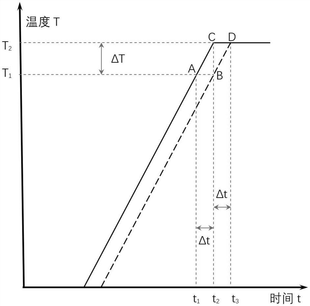
[0065] Place the sample to be tested in a temperature-controlled environment, set the temperature rise rate k of the dielectric test environment to increase linearly with time, and the time interval of the dielectric test; during the test, control the temperature of the dielectric test environment As the time increases linearly, at the same time, during the process of the temperature of the sample changing linearly with time, the dielectric properties of the sample at the preset frequency are intermittently tested at set time intervals, and the records are recorded at different temperatures. The dielectric spectrum of is saved as a data file;

[0066] Calibrate the difference ΔT between the temperature sensor test temperature of the current test and the actual temperature of the sample to be tested;

[0067] After deducting the difference between the test temperature of the temperature sensor and the actual temperature of the sample to be tested for each temperature value in t...


PUM


Abstract

The temperature of a dielectric test environment is linearly increased along with time according to a set heating rate, an impedance tester continuously carries out dielectric test on a to-be-tested sample at a set frequency, and a measurement value of a temperature sensor in a variable-temperature test box and dielectric test data of the impedance tester are transmitted to a computer through a connecting line; the computer carries out storage and later analysis, and test data is stored as a data file; a difference value between the test temperature of the temperature sensor in the current test and the actual temperature of the to-be-tested sample is calibrated; and the difference value between the test temperature of the temperature sensor and the actual temperature of the to-be-tested sample is deduced from each temperature measurement value in the data file to obtain the actual temperature of the to-be-tested sample, and finally the actual dielectric temperature spectrum of the to-be-tested sample is obtained under the set frequency. According to the method, the test time is greatly shortened.

Description

technical field [0001] The invention relates to a fast dielectric thermospectrum testing method, which is a further improvement of the invention patent application CN2021102703196. Background technique [0002] The relevant prior art documents of dielectric thermospectrum are listed as follows (not limited to): [0003] Shi Xiang, Du Huiling, Zhang Xi.Development of Atmospheric Environment Dielectric Temperature Spectrum Measurement System[J].Journal of Xi'an University of Science and Technology, 2011(04):459-462467. [0004] Hua Qiang. Development and Application of Low-Temperature Dielectric Spectrum Testing System[D]. Xi'an University of Science and Technology, 2009. [0005] Zhang Chao, Yu Dashu. Study on Dielectric Relaxation Characteristics of PLZT(7 / 40 / 60) Thin Films[J]. Journal of Tianjin Normal University (Natural Science Edition), 2011, 31(3): 41-44. [0006] Li Weiping, Liu Hesheng, Na Bing, et al. Construction of polyvinylidene fluoride-based composite films an...

Claims


Application Information

Patent Timeline
Patent Type & Authority Applications(China)
IPC IPC(8): G01R27/26
CPCG01R27/2617
Inventor 尹海宏周宇祥施天宇赵晨媛邵海宝邓洪海黄静秦琳张振娟
Owner NANTONG UNIVERSITY
Why Eureka
Try Eureka