Integrated circuit resistance detection device

A resistance detection and detection device technology, which is applied in the direction of measuring devices, electronic circuit testing, measuring resistance/reactance/impedance, etc., can solve the problems of reducing the practicability of the device, not having the sorting function, increasing labor costs, etc., to improve practicality performance, avoid manual selection, and improve work efficiency

Inactive Publication Date: 2021-09-07
潘希全
View PDF1 Cites 1 Cited by
  • Summary
  • Abstract
  • Description
  • Claims
  • Application Information

AI Technical Summary

Problems solved by technology

[0006] The object of the present invention is to provide a kind of integrated circuit resistance detection device, to solve the current market integrated circuit resistance detection device proposed by the above-mentioned background technology, the diversification of the types of integrated circuits, including double-sided integrated circuits, so that in the detection Manual flipping is required during the process, thereby reducing work efficiency. For example, CN201820524832.7 is an integrated circuit resistance detection device. When detecting integrated circuits, it can only detect single-sided integrated circuits, thereby reducing the practicability of the device. At the same time, when detecting integrated circuits, unqualified products will be detected, but the general device does not have a sorting function, so manual selection is required, thereby increasing labor costs.

Method used


Image

  • Integrated circuit resistance detection device
  • Integrated circuit resistance detection device
  • Integrated circuit resistance detection device

Examples


Embodiment Construction

[0027] The following will clearly and completely describe the technical solutions in the embodiments of the present invention with reference to the accompanying drawings in the embodiments of the present invention. Obviously, the described embodiments are only some, not all, embodiments of the present invention. Based on the embodiments of the present invention, all other embodiments obtained by persons of ordinary skill in the art without making creative efforts belong to the protection scope of the present invention.

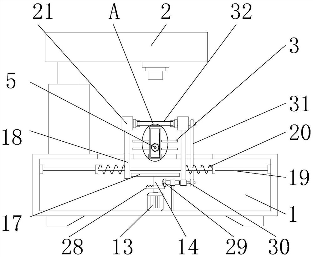
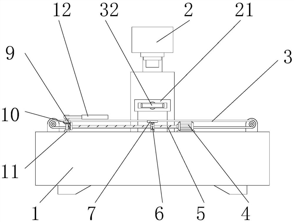
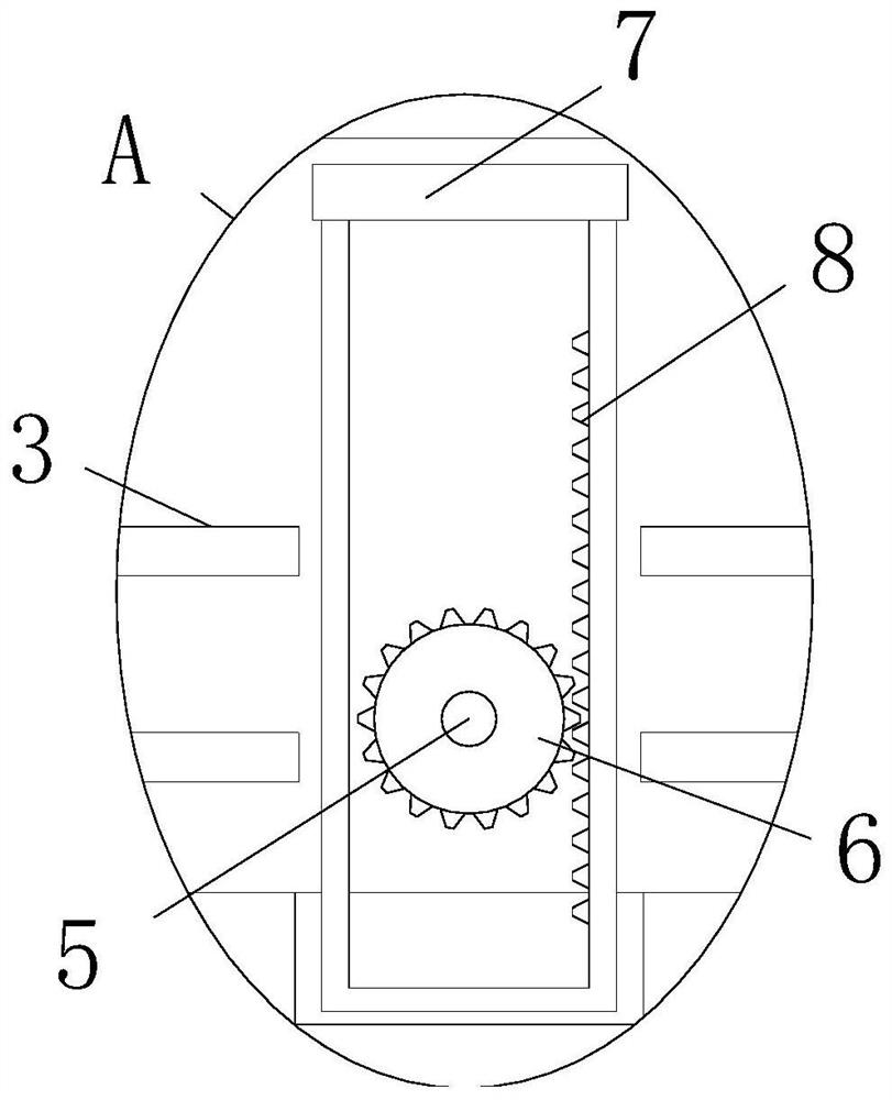
[0028] see Figure 1-7 , the present invention provides a technical solution: an integrated circuit resistance detection device, including a detection device base 1, a connecting rod 5, a main shaft 14 and a cam 17, a detection device main body 2 is installed on the top of the detection device base 1, and the detection device main body 2 is provided with a conveyor belt 3, and the middle part of the bottom of the conveyor belt 3 is installed with a first servo...


PUM


Abstract

An integrated circuit resistance detection device disclosed by the invention comprises a detection device base, a connecting rod, a main shaft and a cam, wherein the top part of the detection device base is provided with a detection device main body, a conveyor belt is arranged right below the detection device main body, the middle part of the bottom part of the conveyor belt is provided with a first servo motor, the top part of the first servo motor is connected with a power gear through a connecting rod, and one side of the power gear is connected with a top plate through a rack. According to the integrated circuit resistance detection device, a supporting block is arranged on the detection device base, and an integrated board main body can be centrally positioned through a positioning block arranged on the supporting block, so that the position deviation of the integrated board main body is avoided, and the accuracy of the device is improved; and through the rotation of a belt pulley group, the belt pulley group drives the supporting block to rotate through a rotating shaft, so that a double-sided integrated board can be conveniently detected, manual turnover is avoided, and the working efficiency is improved.

Description

technical field [0001] The invention relates to the technical field of integrated circuit detection, in particular to an integrated circuit resistance detection device. Background technique [0002] An integrated circuit is a microelectronic device or component that uses a certain process to interconnect components such as transistors, resistors, capacitors, and inductors required in a circuit, and interconnects them together to form a small or several small semiconductor chips or chips. Dielectric substrate, and then encapsulated in a package, to become a microstructure with the required circuit function, in which all components have been structurally integrated, making electronic components towards miniaturization, low power consumption, intelligence and high reliability. It has taken a big step forward in terms of reliability. After the integrated circuit is produced and formed, it is necessary to detect the integrated circuit resistance to prevent defective products from...

Claims


Application Information

Patent Timeline
IPC IPC(8): G01R31/28G01R27/02G01R1/02B07C5/36B65G23/04
CPCG01R31/2893G01R27/02G01R1/02B07C5/36B65G23/04
Inventor 潘希全
Owner 潘希全
Why Eureka
Try Eureka