A special-shaped air hole-assisted multi-core few-mode fiber
A multi-core, few-mode, air hole technology, applied in multi-core fibers, clad fibers, optics, etc., can solve the problems of increasing the complexity of demultiplexing at the receiving end, increasing the splice loss, etc., achieving a simple structure and suppressing inter-mode Crosstalk, low crosstalk effect
- Summary
- Abstract
- Description
- Claims
- Application Information
AI Technical Summary
Problems solved by technology
Method used
Image
Examples
Embodiment 1
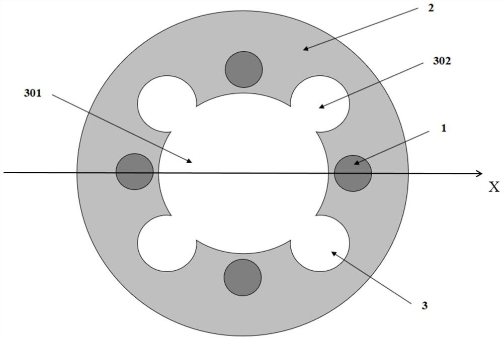
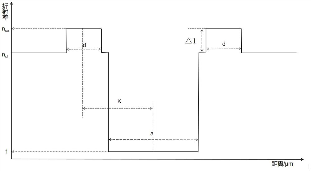
[0056] A special-shaped air hole-assisted multi-core few-mode optical fiber in this embodiment specifically provides a "four-leaf clover"-shaped air-hole-assisted multi-core few-mode optical fiber. The cross-sectional diagram of the optical fiber is as follows figure 1 As shown, the fiber of this embodiment includes a hole-drilled portion in the center of the fiber and a cladding and a few-mode fiber core portion outside the air hole, the hole-drilled portion is a special-shaped air hole, and the diameter of the first air hole in the center is a=50 μm. Four second air holes are arranged on the outer layer of an air hole, and the center of the second air hole is located outside the first air hole, and the first air hole and the second air hole overlap, and the diameter of the second air hole is b=25μm , the distance from the center of the second air hole in the outer layer to the center of the cross-section of the multi-core few-mode fiber assisted by the special-shaped air hole...
Embodiment 2
[0068] This embodiment provides a multi-core few-mode optical fiber assisted by a "four-leaf clover"-shaped air hole. The optical fiber in this embodiment includes a hole-drilled portion in the center of the optical fiber and a cladding and a few-mode fiber core portion outside the air hole. Some of them are special-shaped air holes, the diameter of the first air hole in the center of the optical fiber section is a=50μm, four second air holes are arranged on the outer layer of the first air hole, and the center of the second air hole is located outside the first air hole, And the first air hole and the second air hole coincide, the diameter of the second air hole is b=25μm, and the distance from the center of the second air hole in the outer layer to the center of the cross-section of the multi-core few-mode fiber assisted by the special-shaped air hole is c=30μm , the diameter of the few-mode fiber core is d=14 μm, and the distance from the center of the few-mode fiber core to...
Embodiment 3
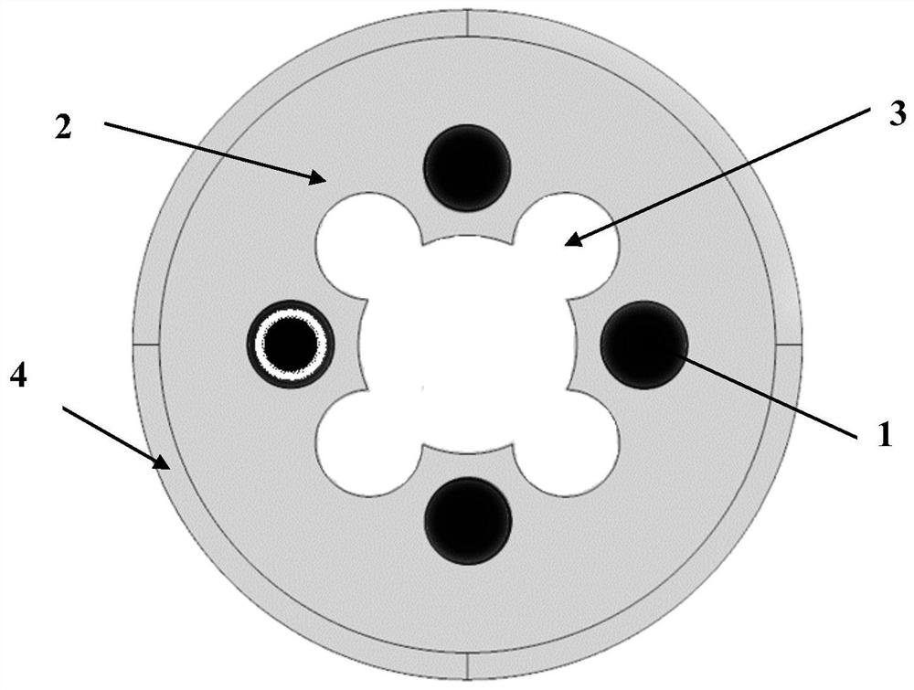
[0074] A special-shaped air hole-assisted multi-core few-mode optical fiber in this embodiment is a "clover"-shaped air-hole-assisted multi-core few-mode optical fiber. The cross-sectional diagram of the optical fiber is as follows: Figure 13 As shown, it includes a cladding, a few-mode fiber core and a special-shaped air hole arranged in the cladding, wherein the multi-core few-mode fiber assisted by the special-shaped air hole is a step-like distribution index structure, and the material of the few-mode fiber core is The germanium-doped silica glass is selected, and the cladding is pure silica glass. The refractive index of the few-mode fiber core > the refractive index of the cladding > the refractive index of the air hole, and the optical fiber cross-section is rotationally symmetrical.
[0075] The special-shaped air hole is located in the center of the optical fiber section. The special-shaped air hole in this embodiment consists of four air holes, of which the first air...
PUM
| Property | Measurement | Unit |
|---|---|---|
| diameter | aaaaa | aaaaa |
| refractive index | aaaaa | aaaaa |
| refractive index | aaaaa | aaaaa |
Abstract
Description
Claims
Application Information
 - R&D
- Intellectual Property
- Life Sciences
- Materials
- Tech Scout
- Unparalleled Data Quality
- Higher Quality Content
- 60% Fewer Hallucinations
Browse by: Latest US Patents, China's latest patents, Technical Efficacy Thesaurus, Application Domain, Technology Topic, Popular Technical Reports.
© 2025 PatSnap. All rights reserved.Legal|Privacy policy|Modern Slavery Act Transparency Statement|Sitemap|About US| Contact US: help@patsnap.com


