
Anti-condensation automatic sanding device

A sand-spreading device and anti-condensation technology, which is used in drying gas layout, locomotives, dryers, etc., can solve the problems of easy agglomeration of sand, unsmooth sand-spreading operation, time-consuming and labor-intensive, etc.

Pending Publication Date: 2021-09-10
HUAIBEI XIANGTAI SCI & TECH
View PDF0 Cites 0 Cited by
  • Summary
  • Abstract
  • Description
  • Claims
  • Application Information

AI Technical Summary

Problems solved by technology

[0004] The object of the present invention is to provide an anti-condensation automatic sanding device, which collects the start-stop state and wheel slippage of the electric locomotive and automatically controls the sanding, without manual sanding, simple operation, and more uniform sanding. The sand in the sand hopper can be loosened and not coagulated by the continuous beating of the sand loosening rod, and the sand in the sand discharge pipe is continuously pounded by the sand loosening rod, which effectively prevents the internal blockage of the sand discharge pipe and achieves no blockage in the sand discharge pipe For the purpose of sand, the baffle blocks the sand in the sand hopper, so that the sand in the sand hopper does not fall out after the power stops, and the sand is dried and stirred to prevent the sand from being damp and agglomerated , to solve the problem that the existing electric locomotive sand spreading device cannot automatically carry out sand spreading, which is time-consuming and laborious, the sand material in the sand bucket is easy to agglomerate, the sand spreading operation is not smooth, and the sand is easy to leak after the sand spreading operation stops

Method used


Image

  • Anti-condensation automatic sanding device
  • Anti-condensation automatic sanding device
  • Anti-condensation automatic sanding device

Examples


Embodiment 1

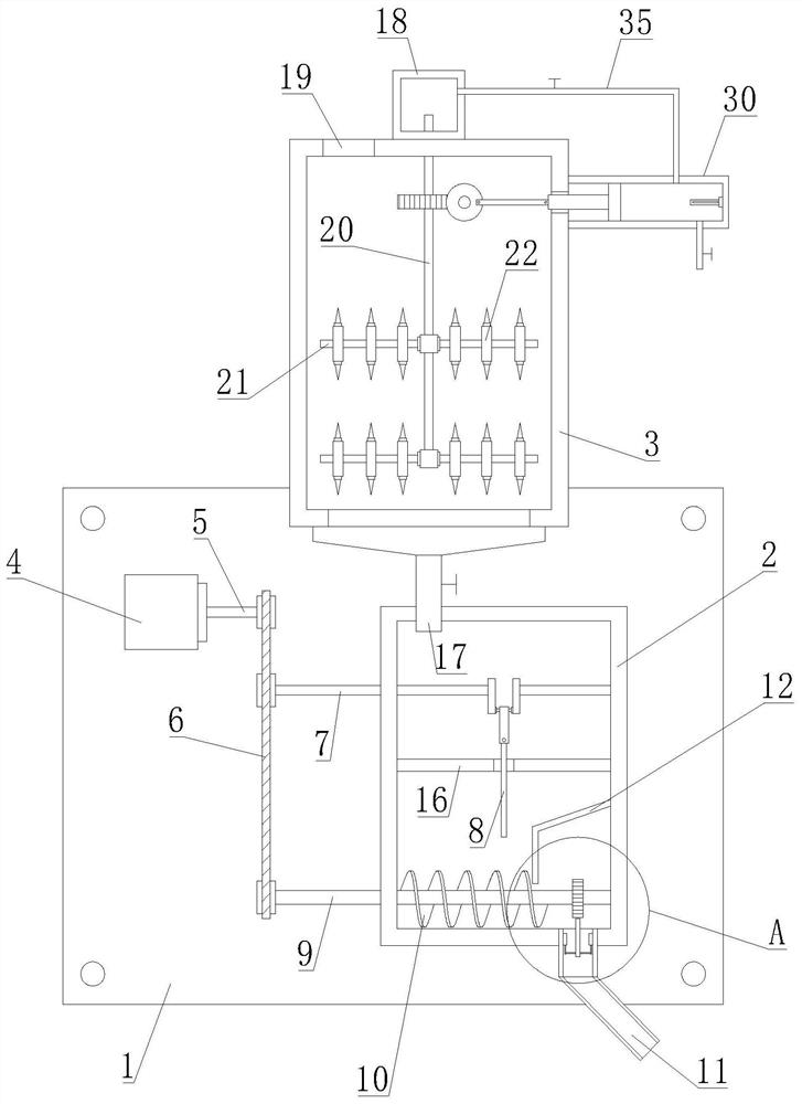
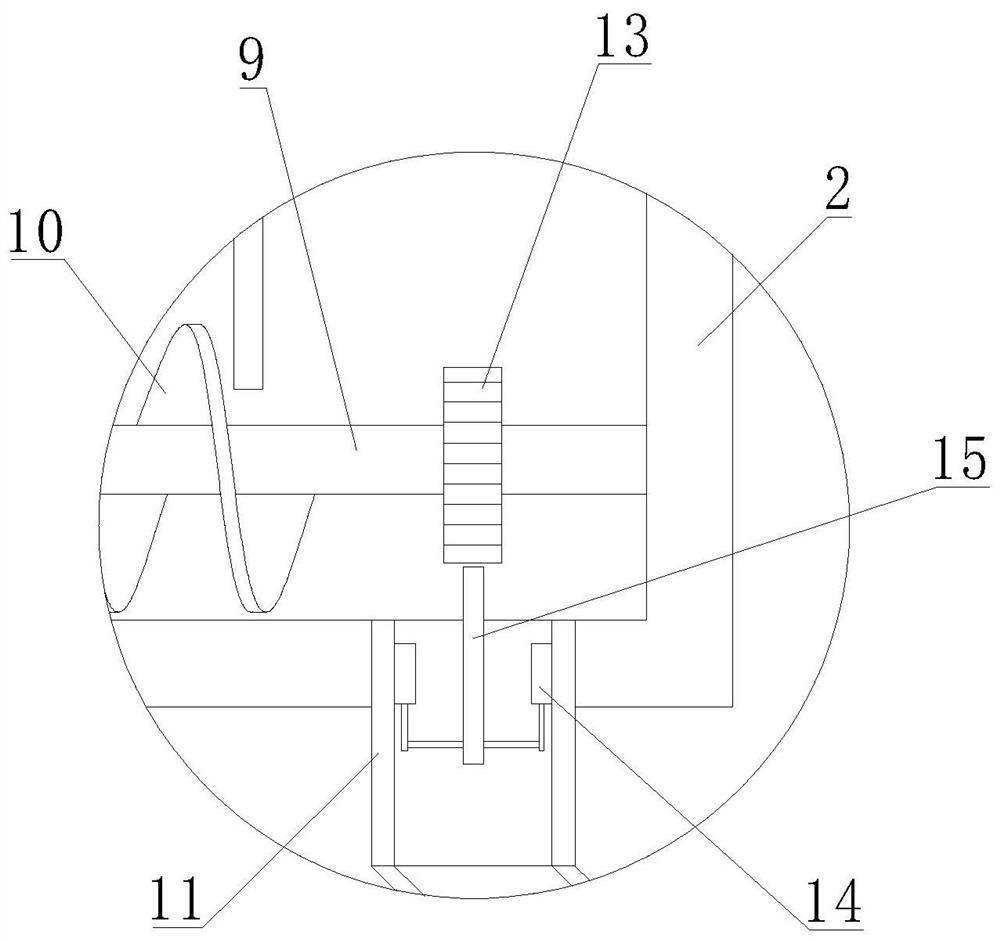
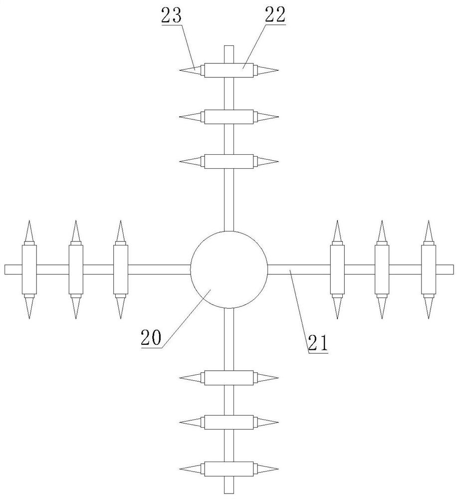
[0032] Such as Figure 1-4As shown, an anti-condensation automatic sand spreading device proposed by the present invention includes a mounting plate 1, a sand holding bucket 2, a sand storage box 3, a sand discharge pipe 11, a sand conveying pipe 17 and a sand filling port 19, and the mounting plate 1 It is fixedly installed on the mining electric locomotive by bolts, and the sand bucket 2 is fixedly installed on the installation plate 1 by bolts. The sand tube 11 spreads the sand in the sand bucket 2 to the upper surface of the rail. The sand can increase the friction between the motor wheel and the rail to ensure the normal start and operation of the electric locomotive. The sand storage box 3 is fixed by bolts Installed on the installation plate 1 and located above the sand bucket 2, sand is stored in the sand storage box 3, and the top of the sand storage box 3 is provided with a sand filling port 19, and sand is added to the sand storage box 3 through the sand filling por...

Embodiment 2

[0037] Such as Figure 5-6 As shown, this embodiment is basically the same as Embodiment 1. Preferably, the outer wall of the sand storage box 3 is fixed with a heating cylinder 30 by bolts, and an electric heating tube 33 is fixedly installed on the side of the heating cylinder 30 away from the sand storage box 3 , the electric heating tube 33 converts electric energy into heat energy to heat the gas in the heating cylinder 30 to make it into hot gas; a piston 32 is slidably arranged in the heating cylinder 30, and the piston 32 slides in the heating cylinder 30, and the piston 32 faces away from the electric One side of the heating pipe 33 is provided with a movable rod 31, and the other end of the movable rod 31 extends into the sand storage box 3 and rotates to connect the pull rod 29. The pull rod 29 pulls or pushes the movable rod 31, and the movable rod 31 makes the piston 32 in the heating cylinder 30 Carry out reciprocating motion in the horizontal direction; the seco...

Embodiment 3

[0039] Such as Figure 7 As shown, this embodiment is basically the same as Embodiment 1. Preferably, the elastic connection mechanism 14 includes a fixed column 1401, an insertion rod 1402, a spring 1403, a connecting rod 1404 and a slot 1405; the fixed column 1401 is vertically arranged on the sand discharge pipe 11, a slot 1405 is provided in the fixed column 1401; the insertion rod 1402 is vertically arranged and inserted into the slot 1405 upwards, the slot 1405 is provided with a guide groove, and the limit slider is located in the guide groove, and the limit slide The block slides up and down along the guide groove, and the inserting rod 1402 is slidably connected with the fixed column 1401 through the limit slider; the top of the slot 1405 is fixedly equipped with a spring 1403, and the bottom end of the spring 1403 is fixedly connected with the inserting rod 1402. Bar 1404 is horizontally arranged on the bottom end of inserting rod 1402 and is connected with loose san...


PUM


Abstract

The invention belongs to the technical field of mining electric locomotives, aims at solving the problems that an existing electric locomotive sanding device cannot automatically carry out sanding, time and labor are wasted, sand in a sand hopper is prone to caking, sanding operation is not smooth, and sand leakage is prone to occurring after sanding operation is stopped, and particularly relates to an anti-condensation automatic sanding device which comprises a mounting plate, a sand containing hopper and a sand storage box. The sand containing hopper is mounted on the mounting plate, a sand discharging pipe is fixedly mounted at the bottom of the sand containing hopper, the sand storage box is located above the sand containing hopper, and a transmission shaft is arranged at the output end of the first motor; a sand loosening crankshaft and a sand feeding roller are rotationally arranged on the sand containing hopper, and the transmission shaft is in transmission connection with the sand loosening crankshaft and the sand feeding roller through a chain; according to the device, sand can be prevented from being affected with damp and agglomerated, sand spraying can be automatically controlled, the sand in the sand containing hopper can be loosened and not condensed, the interior of the sand discharging pipe is prevented from being blocked, the sand in the sand containing hopper does not shakeout after power is stopped, and the normal operation of the mining electric locomotive is effectively guaranteed.

Description

technical field [0001] The invention relates to the technical field of mining electric locomotives, in particular to an anti-condensation automatic sand spreading device. Background technique [0002] Mining electric locomotives are mainly used for long-distance transportation on underground roads and on the ground. It is equivalent to the electric locomotive in railway transportation. The electric locomotive used to transport materials, equipment and personnel is called a mining electric locomotive, and the mine electric locomotive is generally equipped with a sanding device; [0003] At present, when the wheels of the electric locomotive slip during startup or operation, it is necessary to sprinkle sand on the rails through a sand spreading device to increase the friction between the motor wheels and the rails, prevent the wheels from slipping, and ensure the normal startup and operation of the electric locomotive. ;When in use, the driver generally needs to manually shak...

Claims


Application Information

Patent Timeline
IPC IPC(8): B61C15/10F26B21/00
CPCB61C15/10B61C15/107F26B21/001F26B21/006
Inventor 冯学习王相明陈震
Owner HUAIBEI XIANGTAI SCI & TECH
Learn More