
Yarn feeding mechanism for spinning

A yarn and component technology, which is applied in the field of yarn feeding mechanism for spinning, can solve the problems that the operator cannot process quickly, affects the quality of yarn, and the position of the guide pulley is inconvenient to adjust.

Pending Publication Date: 2021-09-10
徐州天虹银联纺织有限公司
View PDF7 Cites 0 Cited by
  • Summary
  • Abstract
  • Description
  • Claims
  • Application Information

AI Technical Summary

Problems solved by technology

[0004] The purpose of the present invention is to provide a yarn feeding mechanism for spinning, to solve the problem that the existing yarn feeding mechanism proposed in the above background technology can only assist in fixing the same type of yarn roller when in use, and the guide pulley The position is inconvenient to adjust, so that the yarn is too loose or too tight, which will affect the entire yarn processing work. At the same time, when the yarn breaks, the operator cannot be reminded, and the operator cannot handle it quickly, which will affect the quality of the yarn in the later stage The problem

Method used

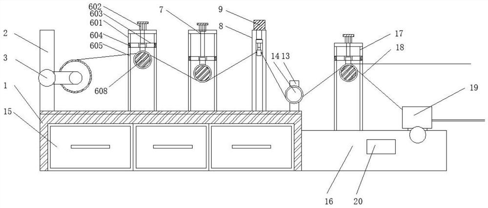
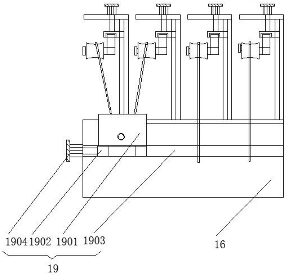
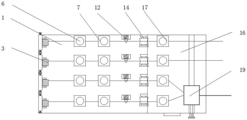

Image

  • Yarn feeding mechanism for spinning
  • Yarn feeding mechanism for spinning
  • Yarn feeding mechanism for spinning

Examples


Embodiment Construction

[0031] The following will clearly and completely describe the technical solutions in the embodiments of the present invention with reference to the accompanying drawings in the embodiments of the present invention. Obviously, the described embodiments are only some, not all, embodiments of the present invention. Based on the embodiments of the present invention, all other embodiments obtained by persons of ordinary skill in the art without making creative efforts belong to the protection scope of the present invention.

[0032] see Figure 1-8 , the present invention provides a technical solution: a yarn feeding mechanism for spinning, such as figure 1 , Figure 4 , Figure 5 , Image 6 with Figure 7As shown, the first support plate 2, the first slide adjustment assembly 6, the second slide adjustment assembly 7, the third support plate 8 and the fourth support plate 13 are fixed on the upper side of the first base 1, and the first support plate 2 is located at the A sli...


PUM


Abstract

The invention discloses a yarn feeding mechanism for spinning, which comprises a first base, a drawing box, a second base and a control box, wherein a first supporting plate, a first sliding adjusting assembly, a second sliding adjusting assembly, a third supporting plate and a fourth supporting plate are fixed to the upper side of the first base, and the first supporting plate is located on the leftmost side of the first sliding adjusting assembly; the third supporting plate is located on the left side of the fourth supporting plate, the first supporting plate is connected with an adjusting assembly in a sliding way, a buzzer is fixed to the upper side of the third supporting plate, a yarn breaking reminding assembly is fixed to the lower side of an electric telescopic rod, and the drawing box is used for storing different yarns; and a third sliding adjusting assembly is fixed to the upper side of the second base. The yarn feeding mechanism for spinning has the advantages that yarn rollers of different lengths can be fixed in an auxiliary mode, the height of the yarns can be adjusted, reminding can be conducted when the yarns are broken, and multiple groups of yarns can be directly doubled.

Description

technical field [0001] The invention relates to the technical field of yarn feeding, in particular to a yarn feeding mechanism for spinning. Background technique [0002] Yarn is a kind of textile, which is processed into a certain fineness product with various textile fibers, and is used for weaving, rope making, thread making, knitting and embroidery, etc. It is divided into staple fiber yarn, continuous filament and so on. Wool yarn and yarn are generally used for weaving woolen sweaters, woolen trousers, woolen vests, scarves, hats and gloves, and weaving various spring and autumn clothing items. In addition to keeping warm, they also have decorative functions. [0003] The existing yarn feeding mechanism can only assist in fixing the same type of yarn rollers during use, and the position of the guide pulley is inconvenient to adjust, so that the yarn is too loose or too tight, which affects the entire yarn processing work. When the yarn breaks, the operator cannot be r...

Claims


Application Information

Patent Timeline
IPC IPC(8): B65H51/08B65H59/10B65H63/036
CPCB65H51/08B65H59/10B65H63/036B65H2701/174B65H2701/31
Inventor 陈明超曹友常史航任树凤王成义
Owner 徐州天虹银联纺织有限公司
Learn More