Foundation pit pre-embedded type double-liquid grouting leaking stoppage device

A double-liquid grouting and pre-embedding technology, which is applied in infrastructure engineering, infrastructure repair, construction, etc., can solve problems such as easy condensation, pipeline blockage, and water-stop wall offset.

Pending Publication Date: 2021-09-10
刘明杰
View PDF4 Cites 1 Cited by
  • Summary
  • Abstract
  • Description
  • Claims
  • Application Information

AI Technical Summary

Problems solved by technology

[0002] The foundation pit is an earth pit excavated at the foundation design position according to the base elevation and foundation plane size. The foundation pit wall support method will be used for foundation pits that are excavated deep or with buildings nearby. The side walls of the foundation pit Set up a concrete water-stop wall, which blocks the exchange of water layers inside and outside the foundation pit. The water-stop wall is provided with a number of retaining piles in front of the foundation pit. There are intervals between the retaining piles, but they can still block and support Therefore, the existing water-stop wall is generally formed by piling with a three-axis mixer pile machine. When the three-axis mixer pile machine is working, it is easy to shift, so that the water-stop wall formed by piling and grouting will be deflected. Gap will be formed at the offset of the water-stop wall. When there is groundwater in the original soil layer outside the water-stop wall, the groundwater mixed with sand and soil will easily flow into the foundation pit along the gap, resulting in piping, so that the original cavitation
[0003] The existing grouting holes are usually drilled on the ground of the original soil layer, and the time for drilling the holes generally takes about 6 hours, and the cement-sodium silicate double slurry used in the grouting process is retained in the grouting pipeline. It is easy to condense for a long time and block the pipeline

Method used


Image

  • Foundation pit pre-embedded type double-liquid grouting leaking stoppage device
  • Foundation pit pre-embedded type double-liquid grouting leaking stoppage device
  • Foundation pit pre-embedded type double-liquid grouting leaking stoppage device

Examples


Embodiment Construction

[0023] The following will clearly and completely describe the technical solutions in the embodiments of the present invention with reference to the accompanying drawings in the embodiments of the present invention. Obviously, the described embodiments are only some, not all, embodiments of the present invention.

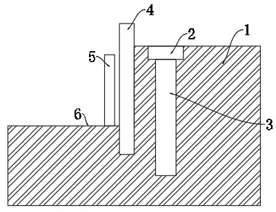
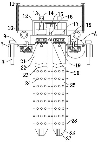
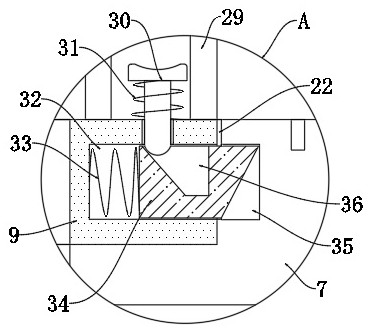
[0024] refer to Figure 1-3 , a pre-buried double-liquid grouting plugging device for foundation pits, including a preset hole 3 arranged in the original soil layer 1 and close to the water stop wall 4, the top of the preset hole 3 is provided with a placement groove 2, and the placement groove 2 Internally connected with a placement plate 7, the placement plate 7 is provided with a mounting groove 22, and the mounting groove 22 is connected with a mounting plate 9, and both sides of the mounting plate 9 are provided with mounting holes 32, and the mounting holes 32 are provided with mounting holes 32 for mounting the mounting plate. 9. The connecting mechanism fixed...


PUM


Abstract

The invention discloses a foundation pit pre-embedded type double-liquid grouting leaking stoppage device. The device comprises a preset hole formed in an original soil layer and close to a water stop wall, a containing groove is formed in the top of the preset hole, a containing plate is connected into the containing groove, a mounting groove is formed in the containing plate, a mounting plate is connected into the mounting groove, and the mounting plate is arranged in the mounting groove, mounting holes are formed in the two sides of the mounting plate, connecting mechanisms used for fixing the mounting plate to the containing plate are arranged in the mounting holes, an opening is formed in the middle of the mounting plate, a second mounting frame located above the opening is fixed to the upper end of the mounting plate, and two connecting sleeves are rotationally connected to the lower end of the second mounting frame; the lower ends of the two connecting sleeves are fixedly sleeved with a cement paste pipe and a water glass pipe correspondingly. The device has the effects of rapidly filling the collapsed position and preventing the ground of the original soil layer from collapsing, and the cement paste and the water glass are mixed more uniformly, so that the mixed condensation filling effect is improved.

Description

technical field [0001] The invention relates to the technical field of anti-seepage and plugging construction for foundation pit enclosure, in particular to a pre-buried type double-liquid grouting plugging device for foundation pits. Background technique [0002] The foundation pit is an earth pit excavated at the foundation design position according to the base elevation and foundation plane size. The foundation pit wall support method will be used for foundation pits that are excavated deep or with buildings nearby. The side walls of the foundation pit Set up a concrete water-stop wall, which blocks the exchange of water layers inside and outside the foundation pit. The water-stop wall is provided with a number of retaining piles in front of the foundation pit. There are intervals between the retaining piles, but they can still block and support Therefore, the existing water-stop wall is generally formed by piling with a three-axis mixer pile machine. When the three-axis ...

Claims


Application Information

Patent Timeline
IPC IPC(8): E02D15/02E02D19/18E02D37/00
CPCE02D15/02E02D19/18E02D19/185E02D37/00E02D2250/003
Inventor 刘明杰
Owner 刘明杰
Why Eureka
Try Eureka