
Air cycle machine

A technology of air cycle machine and protruding ring, which is applied in the direction of air handling equipment, mechanical equipment, aircraft parts, etc., and can solve the problems of low sealing and heat insulation

Pending Publication Date: 2021-09-10
GREE ELECTRIC APPLIANCES INC
View PDF0 Cites 0 Cited by
  • Summary
  • Abstract
  • Description
  • Claims
  • Application Information

AI Technical Summary

Problems solved by technology

[0003] Therefore, the present invention provides an air cycle machine, which can overcome the deficiency of poor sealing and heat insulation between the compressor and the turbine in the related art.

Method used


Image

  • Air cycle machine
  • Air cycle machine
  • Air cycle machine

Examples


Embodiment Construction

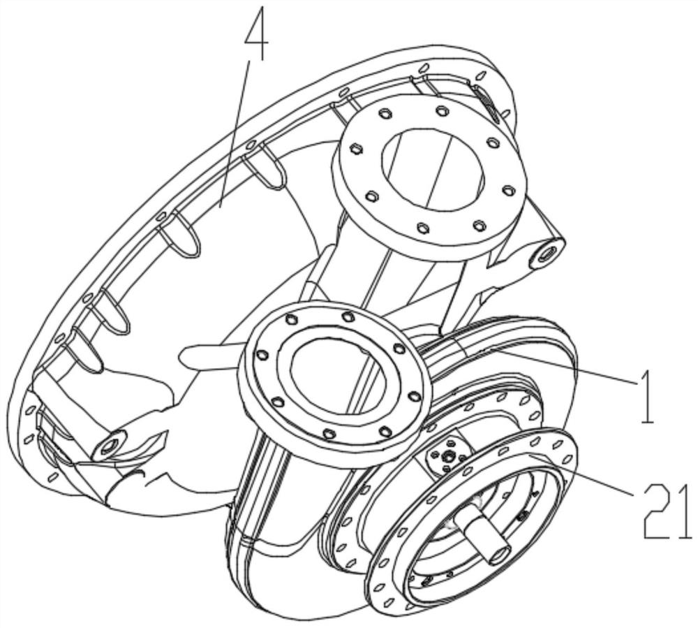
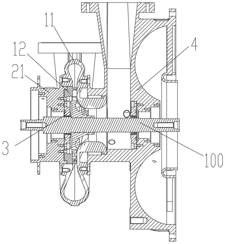
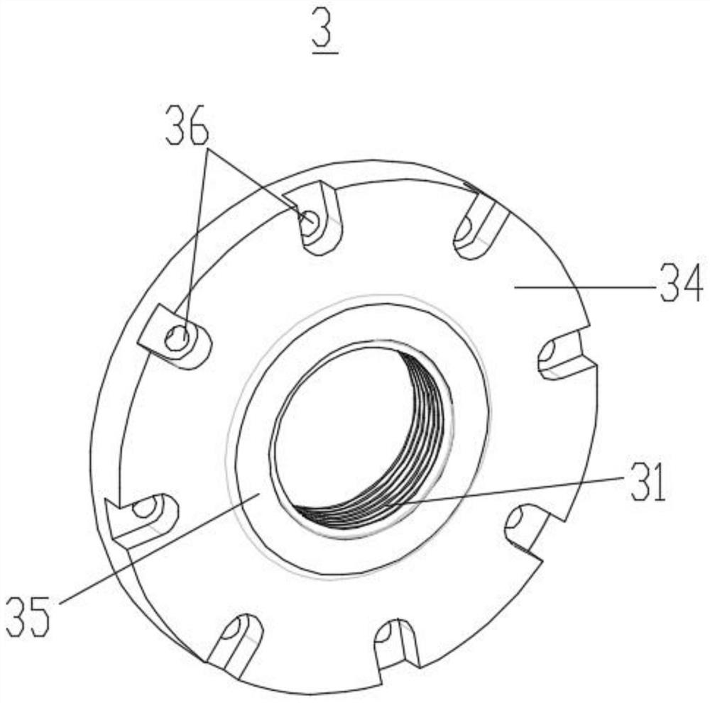
[0024] Combine Figures 1 to 7 , According to the embodiment of the present invention, there is provided an air cycle machine comprising a compressor 1, a turbine (not shown), the fan 4, the compressor 1 and the turbine, the turbine shaft common 4 100, further comprising a bearing housing assembly, said bearing assembly includes a bearing housing seat 21, the bearing block and the first axial side of the bearing housing 21 of the compressor 21 set on the outer peripheral side of the rotating shaft 100 1 the volute 11 is connected to the compressor, the axial bearing housing 21 is connected to a second side of the turbine volute of the turbine, the axial bearing seat 21 on the first side further has a seal member 3, it can be appreciated said first axial side to the one side of the volute 11 of the compressor 21 towards the bearing housing, and said second axial side of the bearing block 21 was toward the side of the turbine volute to 21 connected to the bearing housing through both...


PUM


Abstract

The invention provides an air cycle machine which comprises a compressor and a turbine, the compressor and the turbine share a rotating shaft, the air cycle machine further comprises a bearing seat assembly, the bearing seat assembly comprises a bearing seat, the bearing seat is arranged on the peripheral side of the rotating shaft in a sleeving mode, a first axial side of the bearing seat is connected with a compressor volute of the compressor, a second axial side of the bearing seat is connected with a turbine volute of the turbine, and a sealing piece is further arranged on the first axial side of the bearing seat. According to the air cycle machine, heat transfer between the compressor and the turbine can be effectively reduced, the heat insulation performance is improved, on the other hand, the middle section of the rotating shaft can be effectively supported, and the rotating reliability of the rotating shaft is guaranteed; meanwhile, the sealing piece is located on one side of the compressor, so that the sealing performance between the compressor and the turbine can be improved.

Description

Technical field [0001] The present invention belongs to the field of air conditioning technology, particularly relates to an air cycle machine. Background technique [0002] The air cycle machine by air cooling gas to achieve expansion of external work in a turbine, and drives the compressor and the fan rotation. Compressor, fan, the turbine is a typical three-based air cycle machine, which is characterized by three coaxial. The air flow flows along a next component, the air enters the compressor, through the booster compressor of the turbine raised to the next level, pass through the turbine gas expands to work, to achieve a decrease in temperature. In the related art, in order to prevent play between adjacent compressor and the gas turbine, is provided between the sealing plate, the sealing plate increases the resistance to gas flow, sealing, since the compressor and the turbine assembly is a adjacent components, compressor discharge temperature and high pressure gas, while the...

Claims


Application Information

Patent Timeline
IPC IPC(8): F04D29/05F04D29/08F04D29/58B64D13/06
CPCF04D29/05F04D29/083F04D29/5853B64D13/06B64D2013/0603
Inventor 陈云飞符渡刘茂龙黄建平于艳翠
Owner GREE ELECTRIC APPLIANCES INC
Learn More