
Servo driver

A technology of servo drive and box body, applied in the field of servo drive, can solve the problems of affecting the normal operation of control equipment, affecting the detection efficiency of staff, and consuming time and effort

Pending Publication Date: 2021-09-10
湖北泰和电气有限公司
View PDF0 Cites 0 Cited by
  • Summary
  • Abstract
  • Description
  • Claims
  • Application Information

AI Technical Summary

Problems solved by technology

[0004] In order to overcome the above-mentioned defects of the prior art, the present invention provides a servo driver, which solves the problem that the existing servo driver is generally installed in a control cabinet, and there are multiple bayonets arranged side by side in the cabinet. The driver is inserted into the bayonet, and then the head of the servo driver is locked in the opening of the bayonet by screws, and then the installation is completed. However, when the servo driver needs to be overhauled in this installation method, all the fixing bolts need to be removed again. Move the driver of the private server out of the installation slot for observation and detection. During the detection process, manual support is required for a long time, which is time-consuming and laborious, which greatly affects the detection efficiency of the staff. At the same time, the servo driver is repeatedly disassembled and assembled in the control cabinet through bolts, which is easy to accidentally damage the control cabinet. It is very inconvenient to affect other settings in the device, which in turn affects the normal operation of the control equipment.

Method used


Image

  • Servo driver
  • Servo driver
  • Servo driver

Examples


Embodiment Construction

[0028] The technical solution of this patent will be further described in detail below in conjunction with specific embodiments.

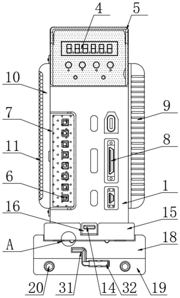
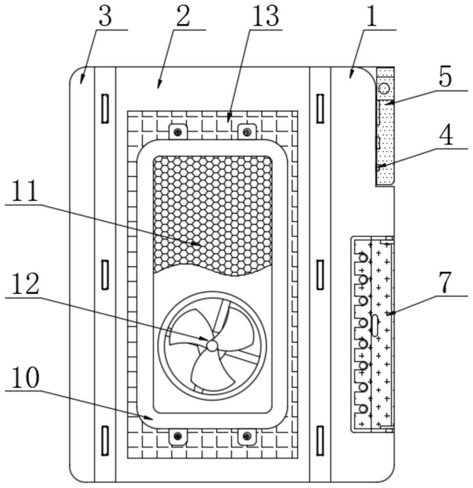
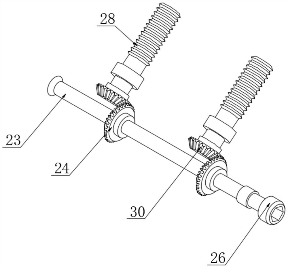
[0029] Such as Figure 1-7As shown, the present invention provides a technical solution: the servo drive includes a first box body 1, a second box body 2 is snapped on the back of the first box body 1, and a third box body is snapped on the back of the second box body 2 Body 3, by setting the first box body 1, the second box body 2 and the third box body 3, the second box body 2 is engaged with the first box body 1 and the third box body 3, so that the device can be easily disassembled In order to facilitate maintenance and processing of the internal circuit board, a control panel 4 is fixedly connected to the top of the front of the first box body 1, and several output interfaces 6 are provided on the left side of the front of the first box body 1. The right side of the box body 2 is provided with several functional interfaces 8, and the right si...


PUM


Abstract

The invention discloses a servo driver, and belongs to the technical field of automation control, the servo driver comprises a mounting seat, a transmission groove is formed in the mounting seat, a rotating rod is movably connected in the transmission groove through a plurality of bearings, two first bevel gears are fixedly connected to the outer surface of the rotating rod, a notch is formed in the front of the right side surface of the mounting seat, a rotating piece is arranged in the notch, and the left side face of the rotating piece is fixedly connected with the right end of a rotating rod. According to the servo driver, by arranging the mounting base, the clamping base, the transmission groove, the rotating rod, the first bevel gear, the rotating piece, the threaded rod, the sliding block and the second bevel gear, the clamping base can move forwards along the upper surface of the mounting base, and therefore all mechanisms on the clamping base can be moved out of a control cabinet conveniently, and therefore, a worker can conveniently observe and detect each mechanism on the clamping seat in all directions. Meanwhile, manual supporting is not needed in the detection process, time and labor are saved, and therefore the detection efficiency of the workers is effectively improved.

Description

technical field [0001] The invention belongs to the technical field of automation control, in particular to a servo driver. Background technique [0002] Servo drive, also known as "servo controller" and "servo amplifier", is a controller used to control servo motors. Its function is similar to that of frequency converters on ordinary AC motors. It is a part of the servo system and is mainly used in A high-precision positioning system generally controls the servo motor through three methods of position, speed and torque to achieve high-precision transmission system positioning. It is currently a high-end product of transmission technology. Servo drives are an important part of modern motion control. It is widely used in automation equipment such as industrial robots and CNC machining centers. The existing servo driver is generally installed in the control cabinet, and there are multiple bayonets arranged side by side in the cabinet. During installation, the staff inserts th...

Claims


Application Information

Patent Timeline
Patent Type & Authority Applications(China)
IPC IPC(8): G05B19/414
CPCG05B19/4142G05B2219/34013
Inventor 骆仁星骆辰李军毕方坤叶劲
Owner 湖北泰和电气有限公司
Learn More