
Cooling liquid blowing device for testing automobile battery assembly

A technology for automobile batteries and coolants, which is applied in household refrigeration devices, cooling fluid circulation devices, measuring devices, etc., can solve problems such as unstable air pressure, increased air pressure in storage tanks, and easy obstruction of cooling liquid return.

Pending Publication Date: 2021-09-10
苏州物睿科技有限公司
View PDF0 Cites 0 Cited by
  • Summary
  • Abstract
  • Description
  • Claims
  • Application Information

AI Technical Summary

Problems solved by technology

[0003] Most of the liquid cooling systems currently used in the laboratory use the liquid purge function to increase the cooling rate. The existing liquid purge device will cause the air pressure inside the device to be unstable during the cooling process. The medium coolant will enter the coolant storage tank together with the purged air, which will cause the air pressure in the storage tank to rise, and the return flow of the coolant will be easily blocked

Method used


Image

  • Cooling liquid blowing device for testing automobile battery assembly
  • Cooling liquid blowing device for testing automobile battery assembly
  • Cooling liquid blowing device for testing automobile battery assembly

Examples


Embodiment 1

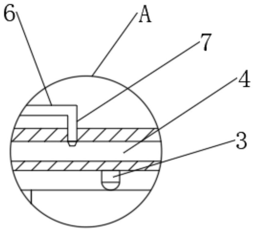
[0024] Such as Figure 1-3 As shown, a cooling liquid purging device for automobile battery assembly test includes a mounting shell 1, a mounting groove 2 is arranged in the mounting shell 1, batteries are uniformly arranged in the mounting groove 2, and the mounting groove 2 The top of the cooling tank 4 is provided with a cooling tank 4, and the cooling tank 4 is horizontally attached to the upper side of the installation tank 2. The blocking block 5 is evenly arranged in the cooling tank 4, and the fan 8 is provided on the side of the cooling tank 4. The fan 8 is connected to the air guide pipe 9, the end of the cooling tank 4 is provided with an air outlet 10, the air outlet 10 is connected to the air guide pipe 9, the blocking block 5 is arranged inclined to the left, and the cooling The left side of the tank 4 is provided with a pressure-stabilizing cylinder 16, and the left end of the cooling tank 4 is horizontally connected with a return pipe 11, and the return pipe 11...

Embodiment 2

[0035] This embodiment is a further improvement and limitation of embodiment 1 on the basis of embodiment 1.

[0036] A coolant purging device for automotive battery assembly testing, comprising a mounting case 1, a mounting groove 2 is arranged in the mounting case 1, batteries are evenly arranged in the mounting groove 2, and the top of the mounting groove 2 is arranged There is a cooling groove 4, and the cooling groove 4 is horizontally attached to the upper side of the installation groove 2, and a blocking block 5 is uniformly arranged in the cooling groove 4, and a fan 8 is arranged on the side of the cooling groove 4, and the fan 8 8 is connected with the air guide pipe 9, and the end of the cooling tank 4 is provided with an air outlet 10, and the air outlet 10 is connected with the air guide pipe 9, and the blocking block 5 is arranged inclined to the left, and the cooling tank 4 The left side is provided with a pressure stabilizing cylinder 16, and the left end of th...


PUM


Abstract

The invention discloses a cooling liquid blowing device for testing an automobile battery assembly, relates to the technical field of automobile battery testing, and mainly aims to solve the problems that the internal pressure intensity of a cooling blowing device is unstable and the backflow of cooling liquid is influenced during existing automobile battery testing. The device comprises a mounting shell, a mounting groove is formed in the mounting shell, batteries are evenly arranged in the mounting groove, a cooling groove is formed in the top of the mounting groove, the cooling groove is horizontally attached to the upper side of the mounting groove, stopping blocks are evenly arranged in the cooling groove, a draught fan is arranged on the side edge of the cooling groove, the fan is connected with an air guide pipe, an air outlet is formed in the end of the cooling groove and connected with the air guide pipe, the stopping blocks are obliquely arranged leftwards, a pressure stabilizing cylinder is arranged on the left side of the cooling groove, the left end of the cooling groove is horizontally connected with a backflow pipe, the backflow pipe is connected with a cooling box, and cooling liquid is injected into the cooling box.

Description

technical field [0001] The invention relates to the technical field of automobile battery testing, in particular to a cooling liquid purging device for automobile battery assembly testing. Background technique [0002] As the energy storage element of the electric vehicle, the performance of the power battery directly affects the performance of the electric vehicle. In the vehicle working mode, when the temperature of the external environment and the battery assembly is high or low, the cooling / heating system will cool down or heat up the battery assembly, so as to ensure that its performance will not be greatly affected. In order to truly simulate the working environment of the battery assembly in the real vehicle state, when testing the performance of the battery assembly in the laboratory, it is necessary to add a liquid cooling or heating system to adjust its temperature. [0003] Most of the liquid cooling systems currently used in the laboratory use the liquid purge f...

Claims


Application Information

Patent Timeline
IPC IPC(8): H01M10/613H01M10/6567G01R31/385F25D17/02B01D46/12B01D53/04B01D53/26
CPCH01M10/613H01M10/6567G01R31/385F25D17/02B01D53/261B01D46/12B01D53/04Y02E60/10
Inventor 李高鹏
Owner 苏州物睿科技有限公司
Learn More