Integrated lens antenna and communication equipment

A technology that integrates lenses and antennas. It is applied in the directions of antennas, antenna arrays, and antenna arrays that are energized separately. It can solve problems such as the inability to achieve continuous angular scanning.

Pending Publication Date: 2021-09-10
SHENZHEN SUNWAY COMM
View PDF0 Cites 0 Cited by
  • Summary
  • Abstract
  • Description
  • Claims
  • Application Information

AI Technical Summary

Problems solved by technology

When multi-angle feeding is required, multiple ports need to be added; however, even if multiple ports can be added to achieve multi-angle beam scanning, there will still be some angles that cannot be scanned, so angular continuous scanning cannot be achieved

Method used


Image

  • Integrated lens antenna and communication equipment
  • Integrated lens antenna and communication equipment
  • Integrated lens antenna and communication equipment

Examples


Embodiment 1

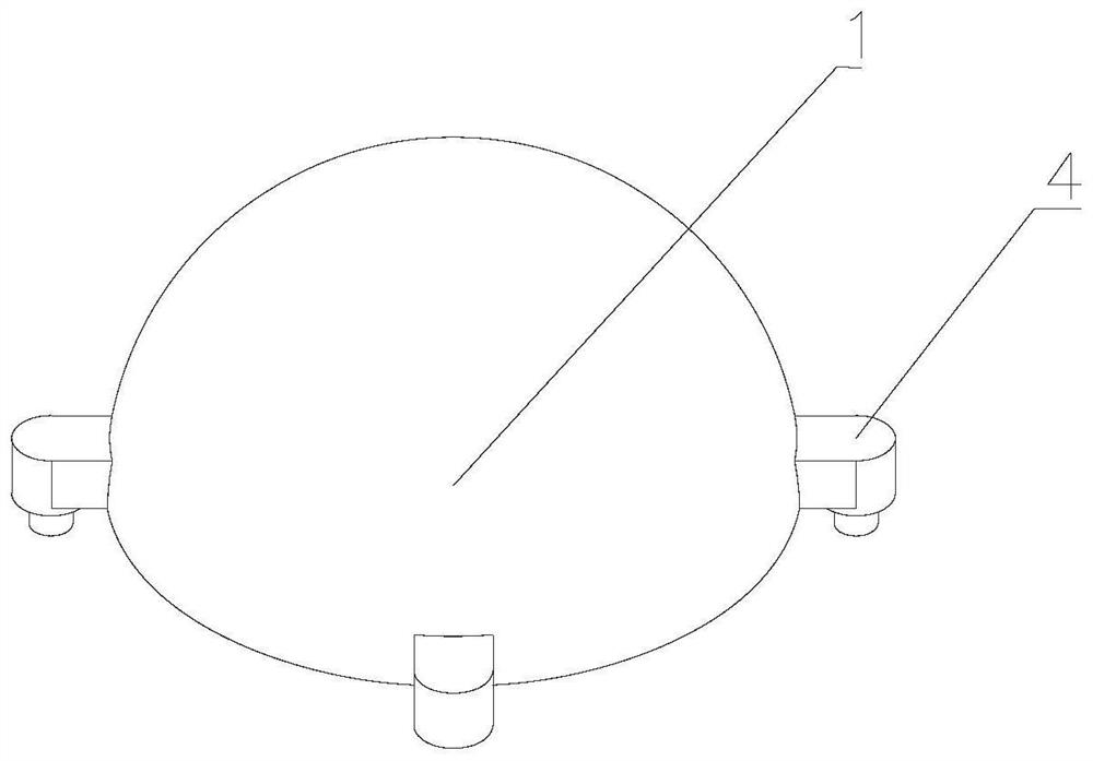
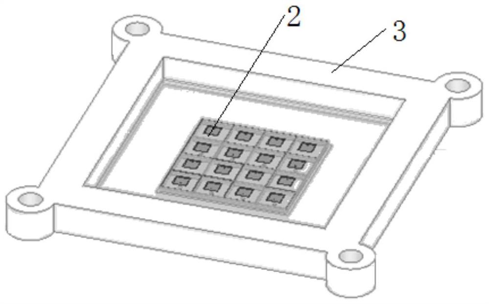
[0051] Please refer to figure 1 as well as figure 2 , an integrated lens antenna, comprising a first dielectric lens 1, a microstrip radiation unit 2 and a base 3;

[0052] The microstrip radiation unit 2 is arranged on one side of the base 3 and is located in the base 3; the base 3 is rectangular and has a rectangular groove inside, and the microstrip radiation unit 2 is arranged on the base 3. In the rectangular groove, there is a height difference between the microstrip radiation unit 2 and the base 3;

[0053]The first dielectric lens 1 is a rotationally symmetrical structure, and the main body of the first dielectric lens 1 is hemispherical; the surface of the hemispherical medium can obtain parallel beams by calculating Snell's law, and by adjusting the first medium The distance between the lens 1 and the microstrip radiation unit 2 enables the first dielectric lens 1 to emit parallel beams; the first dielectric lens 1 can be made of a single dielectric constant mater...

Embodiment 2

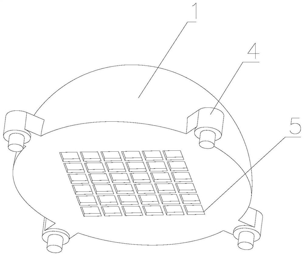
[0058] The difference between this embodiment and the first embodiment is that a dielectric constant buffer layer 5 is also provided;

[0059] The plane side of the first dielectric lens 1 is provided with a dielectric constant buffer layer 5;

[0060] Please refer to image 3 , the dielectric constant buffer layer 5 is an array of recessed grooves; the array of recessed grooves corresponds to the position of the microstrip radiation unit 2; the array of recessed grooves is distributed in a grid; the array of recessed grooves is rectangular;

[0061] Specifically, according to the area of ​​the plane side of the first dielectric lens 1, an array of concave grooves of a corresponding size is set; the array of concave grooves is a 6×6 square array of concave grooves; two sides are respectively parallel to the four sides of the rectangle formed by the microstrip radiation unit 2;

[0062] Wherein, the dielectric constant buffer layer 5 is not limited to an array of recessed gro...

Embodiment 3

[0064] The difference between this embodiment and Embodiment 1 or 2 is that it also includes a second dielectric lens 6;

[0065] Please refer to Figure 4 , the second dielectric lens 6 is a rotationally symmetrical structure, the main body of the second dielectric lens 6 is cylindrical, and its shape is adapted to the first dielectric lens 1; one side of the second dielectric lens 6 It is connected to the plane side of the first dielectric lens 1, and the other side is connected to the base 3;

[0066] Specifically, the dielectric constant and material of the second dielectric lens 6 are the same as those of the first dielectric lens 1, and the hemi-warp is the same as the hemi-warp of the first dielectric lens 1; the first dielectric lens 1 After being connected with the second dielectric lens 6, it can be equivalent to an ellipsoidal dielectric lens; according to the ray tracing theory, when the electromagnetic wave radiated by the microstrip radiation unit 2 passes throu...


PUM


Abstract

The invention discloses an integrated lens antenna, which comprises a first dielectric lens, a microstrip radiation unit and a base, the microstrip radiation unit is arranged at one side of the base and located in the base; the first dielectric lens is of a rotational symmetry structure, and a main body of the first dielectric lens is hemispherical; the plane side of the first dielectric lens is arranged at the other side, far away from the micro-strip radiation unit, of the base, and is spaced from the micro-strip radiation unit; therefore, a certain height difference exists between the hemispherical dielectric lens and the microstrip radiation unit, the influence of the dielectric lens on the impedance matching performance of the microstrip radiation unit is reduced, and the hemispherical rotational symmetric structure can convert the radiation beam of the microstrip radiation unit into a parallel beam; therefore, the radiation beam can realize continuous scanning in the two-dimensional direction and can be converged, the gain of the lens antenna is improved, and the continuous scanning in the two-dimensional direction of the antenna is realized.

Description

technical field [0001] The invention relates to the field of antennas, in particular to an integrated lens antenna and communication equipment. Background technique [0002] The lens antenna is an antenna capable of changing the beam plane of the passing electromagnetic wave, and it is widely used in various wireless communication systems. [0003] At present, integrated lens antennas usually use multi-port feeds to realize beam scanning, that is, one port feeds to realize beam radiation at one angle. When multi-angle feeding is required, multiple ports need to be added; however, even if multiple ports can be added to achieve multi-angle beam scanning, there will still be some angles that cannot be scanned, so angular continuous scanning cannot be achieved. Contents of the invention [0004] The technical problem to be solved by the present invention is to provide an integrated lens antenna to realize continuous scanning in the two-dimensional direction of the antenna. ...

Claims


Application Information

Patent Timeline
Patent Type & Authority Applications(China)
IPC IPC(8): H01Q1/36H01Q1/12H01Q19/06H01Q15/08H01Q21/06
CPCH01Q1/36H01Q1/12H01Q19/06H01Q15/08H01Q21/061
Inventor 唐小兰赵伟谢昱乾杨扬
Owner SHENZHEN SUNWAY COMM
Why Eureka
Try Eureka