An incident optical system for a near-infrared spectrum sensing node and its working method
A near-infrared spectrum and sensing node technology, applied in the field of incident optical systems, to achieve the effects of easy installation integration, easy installation, and low price
- Summary
- Abstract
- Description
- Claims
- Application Information
AI Technical Summary
Problems solved by technology
Method used
Image
Examples
Embodiment 1
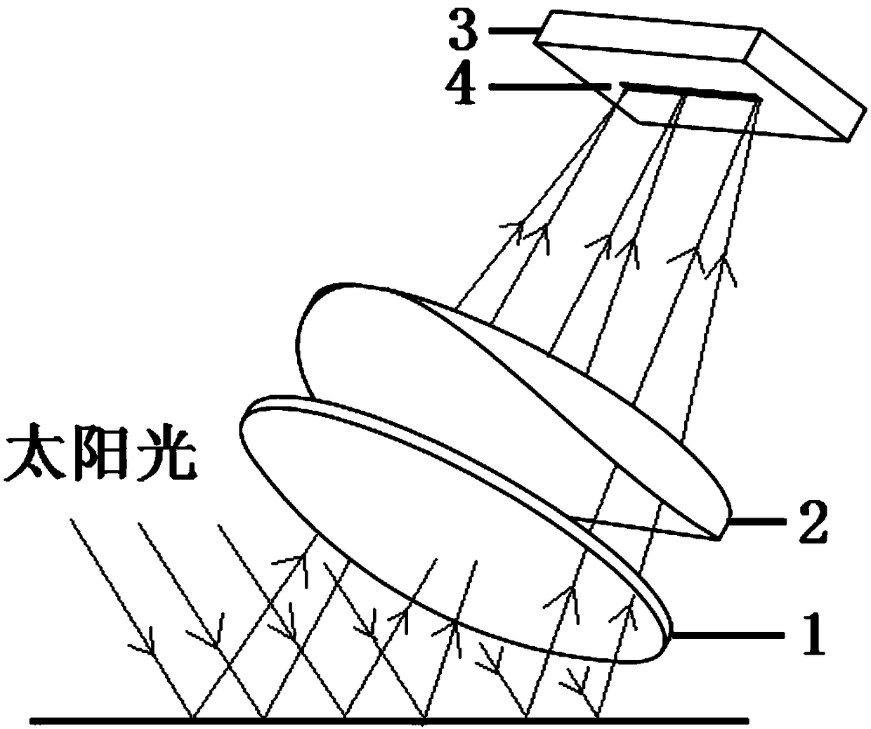
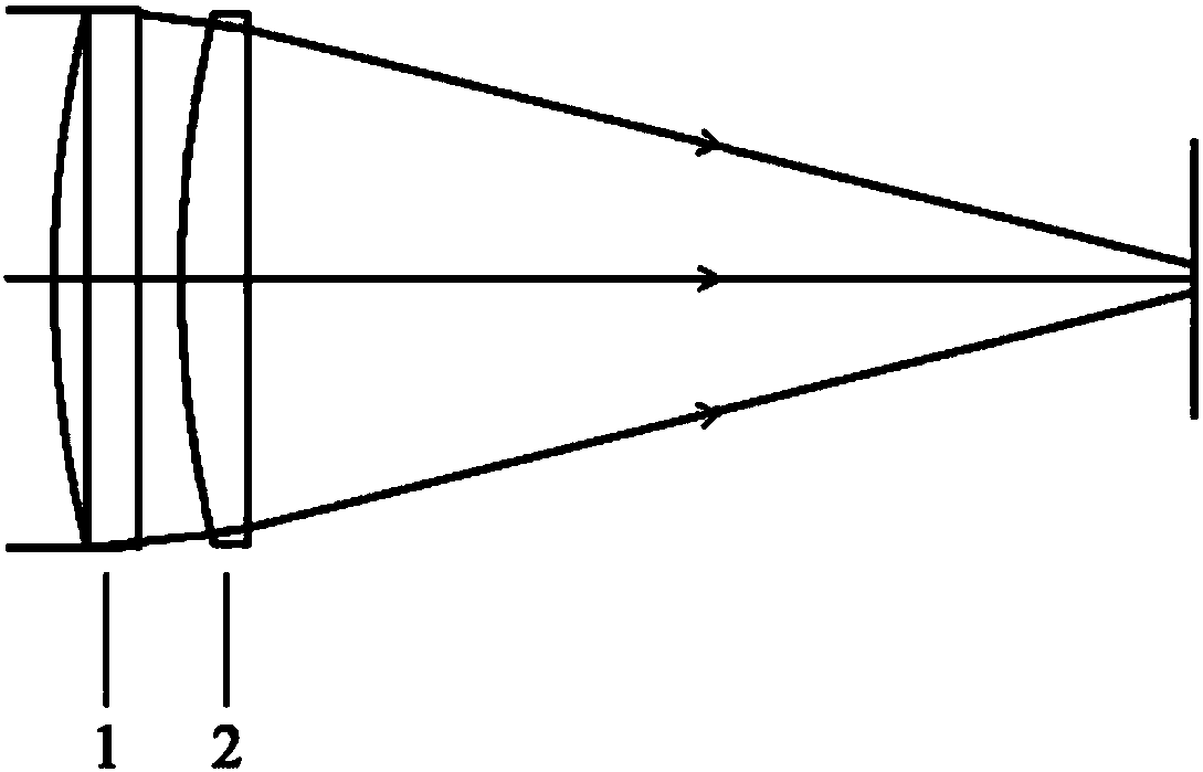
[0031] An incident optical system for a near-infrared spectrum sensing node, including a near-infrared light source, a plano-convex lens 1 arranged in sequence along the propagation direction of incident light, a positive cylindrical mirror 2 and a photosensitive element 3, and the incident light passes through the planar The convex side and the plane side of the convex lens 1 , the incident light passes through the convex cylinder side and the plane side of the positive cylindrical mirror 2 in sequence, and the near-infrared light finally enters the photosensitive element 3 .
[0032] The near-infrared light source is reflected light after sunlight irradiates the object to be detected, specifically near-infrared light with a wavelength range of 1350nm to 1550nm.
Embodiment 2
[0034] A kind of incident optical system for near-infrared spectrum perception node as described in embodiment 1, its difference is that, the curvature radius of the convex side of described plano-convex lens 1 is 52.51mm; The convex column of described positive cylindrical mirror 2 The radius of curvature on the surface side is 51.85 mm.
[0035] The plano-convex lens 1 has a focal length of 101.6 mm, a central thickness of 4 mm, and a clear aperture of 25.4 mm.
[0036] The positive cylindrical mirror 2 has a focal length of 100 mm, a central thickness of 3.16 mm, and a clear aperture of 25 mm.
[0037] The center-to-center distance between the plano-convex lens 1 and the positive cylindrical mirror 2 is 5.58 mm, and the total distance from the apex of the convex side of the plano-convex lens 1 to the photosensitive element 3 is 53.76 mm.
Embodiment 3
[0039] An incident optical system for a near-infrared spectrum sensing node as described in Example 2, the difference is that the plano-convex lens 1 and the positive cylindrical mirror 2 are both made of H-K9L crown glass. The focal length tolerance of the plano-convex lens 1 is ±1%, the size tolerance is 0.0-0.1mm, and the center thickness tolerance is ±0.1mm; the focal length tolerance of the positive cylindrical mirror 2 is ±2%, the size tolerance is 0.0-0.1mm, and the center thickness tolerance is ±2%. ±0.1mm.
[0040] Both sides of the plano-convex lens 1 and the positive cylindrical mirror 2 are coated with an anti-reflection film in the wavelength range of 1050nm to 1620nm, and the transmittance of the single-layer anti-reflection film is greater than 99.5%.
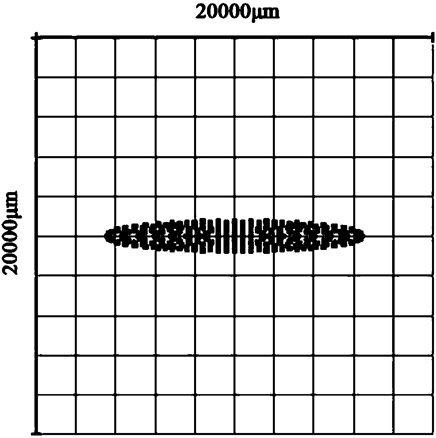
[0041] The photosensitive element 3 is a 256-element linear InGaAs detector with a 64-channel linear gradient filter, and its photosensitive surface 4 is a rectangle with a size of 12.8mm×0.5mm.
[0042]In combi...
PUM
 Abstract
Description
Claims
Application Information
 - R&D
- Intellectual Property
- Life Sciences
- Materials
- Tech Scout
- Unparalleled Data Quality
- Higher Quality Content
- 60% Fewer Hallucinations
Browse by: Latest US Patents, China's latest patents, Technical Efficacy Thesaurus, Application Domain, Technology Topic, Popular Technical Reports.
© 2025 PatSnap. All rights reserved.Legal|Privacy policy|Modern Slavery Act Transparency Statement|Sitemap|About US| Contact US: help@patsnap.com


