Supercharge Your Innovation With Domain-Expert AI Agents!

Automatic material roll stacking device

An automatic stacking and material roll technology, which is applied in the direction of transportation, packaging, and object stacking, can solve problems such as low work efficiency, unstable stacking quality, and high labor intensity.

Active Publication Date: 2021-09-14
ALFAR SUZHOU AUTOMATION TECH
View PDF9 Cites 0 Cited by
  • Summary
  • Abstract
  • Description
  • Claims
  • Application Information

AI Technical Summary

Problems solved by technology

[0004] The technical problem to be solved by the present invention is: in order to overcome the disadvantages of manual re-stacking of paper rolls in the prior art, such as high labor intensity, low work efficiency, and unstable stacking quality, an automatic stacking device for material rolls is provided

Method used


Image

  • Automatic material roll stacking device
  • Automatic material roll stacking device
  • Automatic material roll stacking device

Examples


Embodiment 1

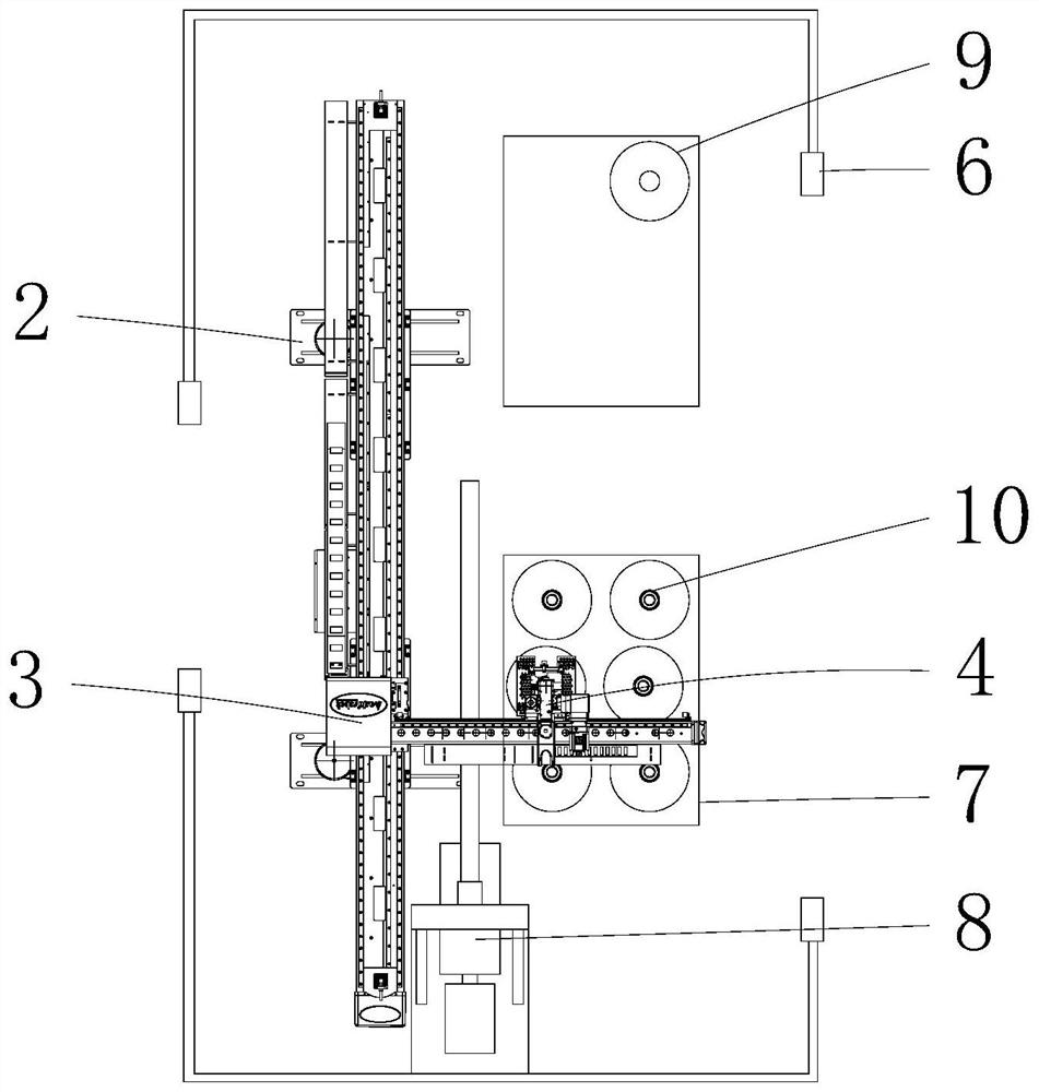
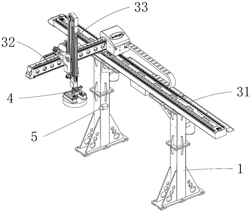
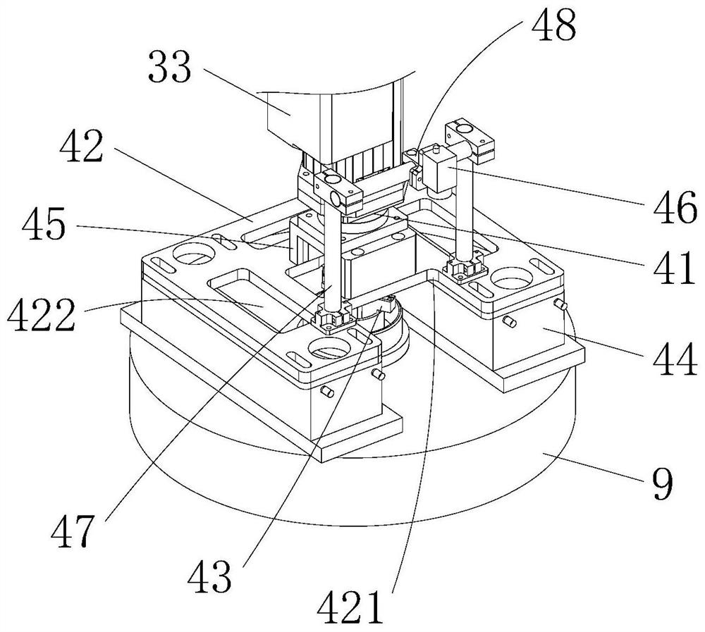
[0030] Such as Figure 1-4 As shown, the present invention provides an automatic stacking device for material rolls, which includes a fence 1 and a vertical frame 2 arranged in the fence 1. It is characterized in that the vertical frame 2 is provided with a The traveling mechanism 3; preferably, the traveling mechanism 3 includes an X-axis linear module 31 erected on the top of the vertical frame 2, a Y-axis linear module 32 installed on the X-axis linear module 31, and a Y-axis linear module installed on the Y-axis linear module. The Z-axis lifting assembly 33 on the group 32 realizes precise stroke control. The walking mechanism 3 is provided with a material suction mechanism 4, and the vertical frame 2 is also provided with a code scanning mechanism 5 that cooperates with the material suction mechanism 4; The coding of the product 9 can be calculated to obtain the specific position of the product 9.

[0031] The suction mechanism 4 includes a steering motor 41 vertically ...

Embodiment 2

[0038] Such as figure 1 , Figure 5As shown, the present invention also provides an automatic stacking device for material rolls, which is different from Embodiment 1 in that: a material rack 7 is provided in front of the vertical frame 2, and an air supply mechanism 8 is provided between the material rack 7 and the scanning mechanism 5; Preferably, the air supply mechanism 8 includes a fixed frame 81 arranged on one side of the vertical frame 2, an air supply device 82 arranged at the bottom of the fixed frame 81, a rotating assembly 83 and an air pipe 84 arranged at the top of the fixed frame 81, and the air pipe 84 Horizontally arranged between the material rack 7 and the code scanning mechanism 5, the air duct 84 is provided with an air inlet 841 connected to the air supply device 82, the air duct 84 is provided with a plurality of air outlets 842 along the length direction, and one end of the air duct 84 Sealed, the other end is connected with the rotating assembly 83. ...


PUM


Abstract

The invention relates to an automatic material roll stacking device which comprises a surrounding net and a vertical frame arranged in the surrounding net. A walking mechanism capable of moving in the X-axis direction, the Y-axis direction and the Z-axis direction is arranged on the vertical frame, a material suction mechanism is arranged on the walking mechanism, and a code scanning mechanism matched with the material suction mechanism is further arranged on the vertical frame. The material suction mechanism comprises a steering motor vertically installed below the walking mechanism, an installation plate horizontally arranged below the steering motor, a pneumatic chuck arranged in the center of the installation plate and suction plates arranged on the two sides of the lower end of the installation plate respectively, and a U-shaped base connected with the steering motor is fixed to the installation plate. The mounting plate is provided with a notch between the two suction plates, and a center positioning CCD facing the ground is arranged above the notch. According to the automatic material roll stacking device, manual stacking is replaced by an automatic machine, the labor intensity is greatly reduced, and the product stacking efficiency is improved; the stacking positions of the products are obtained through code scanning, orderly and stable stacking can be achieved, and follow-up shipment of the products is facilitated.

Description

technical field [0001] The invention relates to the field of cigarette case production, in particular to an automatic stacking device for material rolls. Background technique [0002] as attached Figure 6 As shown, after the production of the product (gold foil cigarette paper roll) is completed, it needs to be stacked on the material board for a period of time to dissipate the flavor. Spacers are separated. After the deodorization is completed, the spacer on the product needs to be taken out, and the product is moved to another material board for orderly stacking to facilitate shipment. [0003] At present, the re-stacking operation of the above products is mainly done manually, which has the disadvantages of high labor intensity and low work efficiency, and the stability of product stacking is poor, and it is difficult to ensure the consistency of the coding position on the product, which affects the shipping process . Contents of the invention [0004] The technical...

Claims


Application Information

Patent Timeline
Patent Type & Authority Applications(China)
IPC IPC(8): B65G57/04
CPCB65G57/04
Inventor 施太郎
Owner ALFAR SUZHOU AUTOMATION TECH
Features
  • R&D
  • Intellectual Property
  • Life Sciences
  • Materials
  • Tech Scout
  • Unparalleled Data Quality
  • Higher Quality Content
  • 60% Fewer Hallucinations
Learn More