Device for testing oil levels of multiple fuel tanks of automatic drilling machine

A technology of fuel tank and fuel tank, which is applied in the direction of displaying liquid level indicator through pressure measurement, etc., can solve the problems of lack of pressure relief and protection, poor operation flexibility, inconvenient to take out the addition barrel, etc.

Active Publication Date: 2021-09-14
ZHEJIANG ZHIGAO MACHINERY
View PDF15 Cites 0 Cited by
  • Summary
  • Abstract
  • Description
  • Claims
  • Application Information

AI Technical Summary

Problems solved by technology

[0003] However, the electrical system of the unit needs to display the real-time fuel position of the fuel tank, output alarm signals for high and low fuel positions, etc., to meet the intelligent control requirements of the electrical system of the unit. The resistance sensor is realized by using a linear sliding rheostat, and the resistance value is controlled by a float. As the oil volume changes, the resistance value will also change accordingly. The controller tests the fuel oil level according to the resistance value tested by the sensor. , to realize display, alarm and other functions, this method is only suitable for the measurement of the fuel volume of a fuel tank with a basic square shape, and is not suitable for the situation where two or more or even special-shaped fuel tanks are connected to store fuel, so electrical intelligence cannot be realized At the same time, most of the fuel tanks are directly fixed on the equipment, and do not have the function of pressure relief and protection. When encountering foreign objects, it is easy to cause damage to the fuel tank, and most of the top of the fuel tank is directly equipped with an end cover, and the sealing port of the end cover is small. When adding oil directly, it is easy to cause oil splashing. At the same time, the vent hole set in the oil tank is set separately. When adding oil, it needs to be opened manually. When the oil is added, it is not convenient to take out the adding barrel in time, and the operation flexibility is poor.

Method used


Image

  • Device for testing oil levels of multiple fuel tanks of automatic drilling machine
  • Device for testing oil levels of multiple fuel tanks of automatic drilling machine
  • Device for testing oil levels of multiple fuel tanks of automatic drilling machine

Examples


Embodiment Construction

[0044] In order to make the technical means, creative features, goals and effects achieved by the present invention easy to understand, the present invention will be further described below in conjunction with specific embodiments.

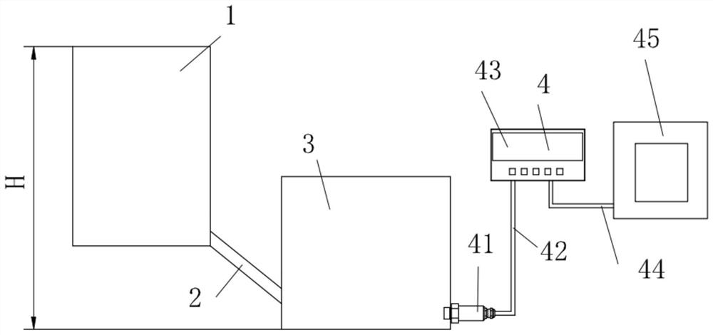
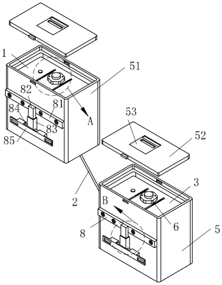
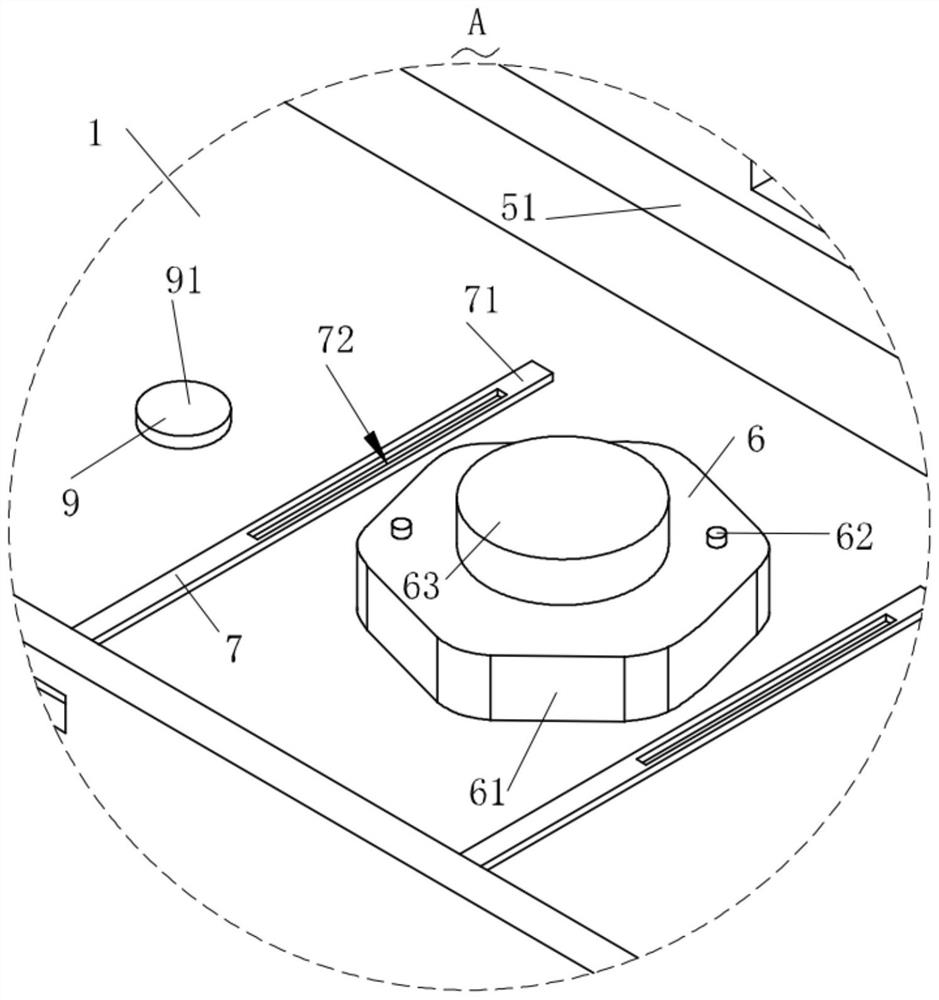
[0045] Such as Figure 1-Figure 11 As shown, a device for testing the oil level of an automatic drilling rig with multiple fuel tanks according to the present invention includes a first fuel tank 1 and a second fuel tank 3, and a connecting pipe 2 is used to guide the first fuel tank 1 and the second fuel tank 3. In general, the bottom end of the second fuel tank 3 is connected with a test structure 4, and both the first fuel tank 1 and the second fuel tank 3 are accommodated and protected by a protective structure 5, and a pressure relief structure 8 is provided on the protective structure 5; Both the first oil tank 1 and the second oil tank 3 are provided with a sealing structure 6 for controlling the sealing of the oil tanks, and the first oil ...


PUM


Abstract

The invention relates to the technical field of oil level testing equipment, in particular to a device for testing the oil levels of multiple fuel tanks of an automatic drilling machine. A first fuel tank and a second fuel tank are included, the first fuel tank and the second fuel tank are communicated through a communicating pipe, and the bottom end of the second fuel tank is connected with a testing structure. The first oil tank and the second oil tank are stored and protected through a protection structure, and a pressure relief structure is arranged on the protection structure. The first oil tank and the second oil tank are provided with sealing structures used for controlling sealing of the oil tanks, the first oil tank and the second oil tank are provided with exhaust structures used for exhausting, and the sealing structures can drive the exhaust structures. The protection structure is provided with a driving structure used for driving a refueling barrel to move. The liquid level testing effect is good, using is stable, oil adding is stable and convenient, the operation efficiency is high, and the pressure resisting and releasing effects are good.

Description

technical field [0001] The invention relates to the technical field of oil level testing equipment, in particular to a device for testing oil levels in multiple fuel tanks of an automatic drilling rig. Background technique [0002] Automatic drilling rig products are widely used in various types of engineering construction, mining, hydropower engineering, tunnel road construction, railway anchoring and other mechanized projects. The working time of continuous operation is at least 8-10 hours. At present, the power of the engine supporting the automatic drilling rig is basically above 300-400kW. According to the calculation of the fuel consumption of the engine, the design capacity of the fuel tank needs to be more than 700-1000 cubic meters to satisfy the user. Use requirements, and when the user is actually using it on site, the volume of the fuel tank is required to be larger to facilitate the actual use of production. With the expansion of the application field of automat...

Claims


Application Information

Patent Timeline
Patent Type & Authority Applications(China)
IPC IPC(8): G01F23/14
CPCG01F23/14
Inventor 余利芳蒋丽伟黄振华
Owner ZHEJIANG ZHIGAO MACHINERY
Why Eureka
Try Eureka