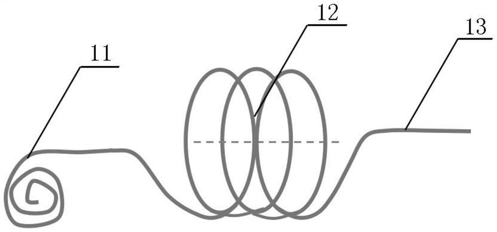
Installation method for fixing sensor in spiral heat transfer pipe

An installation method and sensor technology, which can be applied to instruments, measuring devices, and greenhouse gas reduction, etc., can solve problems such as inability to optimize and change the design, inability to pull sensors, and inability to implement spiral tubes.

Active Publication Date: 2021-09-14
GENERAL ENG RES INST CHINA ACAD OF ENG PHYSICS
View PDF10 Cites 0 Cited by
  • Summary
  • Abstract
  • Description
  • Claims
  • Application Information

AI Technical Summary

Problems solved by technology

[0011] 1. In the traditional installation method, iron wire or multi-strand soft steel wire or enameled wire can enter the last circle of the spiral tube when the sensor is not pulled, and then go in or pull the pulling end. It is impossible to enter the tube. These wires Or the nylon wire forms a huge friction force with the inner surface of the tube, which cannot be pulled, let alone pull the sensor into it;
[0012] 2. The previously designed push tooling for the straight section of the heat transfer tube cannot be implemented in the spiral tube because it relies on the push straight rod at the rear end to push the sensor forward in the tube;
[0013] 3. The designed installation tool without push rod, because the outer diameter of the sensor is relatively large, when it is installed in the installation tool and then dragged into the tube, interference between the

Method used


Image

  • Installation method for fixing sensor in spiral heat transfer pipe
  • Installation method for fixing sensor in spiral heat transfer pipe
  • Installation method for fixing sensor in spiral heat transfer pipe

Examples


Embodiment Construction

[0048]In order to make the purpose, technical solutions and advantages of the embodiments of the present invention clearer, the technical solutions in the embodiments of the present invention will be described clearly and completely below with reference to the accompanying drawings in the embodiments of the present invention. Obviously, the described embodiments are some, but not all, embodiments of the present invention. The components of the embodiments of the invention generally described and illustrated in the drawings herein may be arranged and designed in a variety of different configurations.

[0049] Thus, the following detailed description of the embodiments of the invention provided in the accompanying drawings is not intended to limit the scope of the invention as claimed, but is merely representative of selected embodiments of the invention. Based on the embodiments of the present invention, all other embodiments obtained by those of ordinary skill in the art witho...


PUM


Abstract

The invention discloses an installation method for fixing a sensor in a spiral heat transfer pipe. The method comprises the following steps a preparation process, a process of enabling a main line and an auxiliary line to penetrate through a spiral heat transfer tube, a process of making an installation line knot on the main line, a process of locking and fixing a sensor by using the installation line knot, a process of adjusting the leading-out direction of a second sensor lead to be consistent with the inlet direction, a process of adding the auxiliary line, a finishing process, a process of feeding the sensor into a tube for installation, and an accurate adjustment of the installation position of the sensor. According to the method, a method of locking and fixing the sensor by using the PE wire mounting wire knot is adopted, and the friction force between the PE wire and the surface of the inner wall of the spiral pipe is small, so the PE wire can still be freely dragged in the pipe after being spiral along the spiral pipe as a mounting pull wire; a problem that traditional iron wires or multi-strand soft steel wires or enameled wires and the like adopted in the spiral pipe cannot be freely dragged is solved.

Description

technical field [0001] The invention relates to the technical field of sensor installation, in particular to a method for installing a fixed sensor in a spiral heat transfer tube. Background technique [0002] The steam generator is the main equipment of the primary circuit of the pressurized water reactor nuclear power plant, and is the hub connecting the primary circuit and the secondary circuit. Due to the long-term erosion by the flow of the steam-water mixture, there is a risk of induced flow-induced vibration failure. There are many failure mechanisms of flow-induced vibration, such as vortex shedding, turbulent excitation, and stray bomb instability. Reaching the critical flow rate will cause the heat transfer tube to leak and fail rapidly in a short period of time, affecting the operation safety of equipment and power stations. Therefore, it is necessary to carry out experimental research on the mechanism of flow-induced vibration of the steam generator heat transfe...

Claims


Application Information

Patent Timeline
IPC IPC(8): G01P15/097G01P15/18
CPCG01P15/097G01P15/18Y02E30/30
Inventor 唐俐张利何坤聂飞陈发斌马文慧刘志斌王军赵川梅季锡林杜寿兵
Owner GENERAL ENG RES INST CHINA ACAD OF ENG PHYSICS
Why Eureka
Try Eureka