
Vibration generating device and input unit for video gamke machnie using said device

A technology of vibration generation and input devices, which is applied to fluids that utilize vibrations, input/output processes of data processing, indoor games, etc., can solve the problems of increasing types of parts, high assembly costs, and reducing costs, and reduce the types of parts , Reduce the number of parts, reduce the effect of manufacturing costs

Inactive Publication Date: 2004-01-07
ALPS ALPINE CO LTD
View PDF0 Cites 0 Cited by
  • Summary
  • Abstract
  • Description
  • Claims
  • Application Information

AI Technical Summary

Problems solved by technology

[0010] However, in the above-mentioned structure of two or more motors, for each motor, it is necessary to have the wiring of the substrate, the fixing member that transmits the vibration of the motor to the case and fixes the motor to the case, etc., so parts The number is large, and the assembly cost is high, so it is not conducive to cost reduction
[0011] In addition, in order to produce different vibration states, the specifications of two or more motors must be different. Therefore, the specifications of the eccentric weights are also different. In this way, the types of parts are increased, which is not conducive to reducing costs.
[0012] In addition, in the above structure, space is required to accommodate the motors. The weight of these motors and eccentric weights accounts for a considerable proportion of the weight of the controller, which is not conducive to the miniaturization and weight reduction of the controller, and may reduce the operability of the controller.
[0013] In addition, when other functions are installed in the controller to make it multi-functional, the ratio of the motor housing space to the volume of the controller will become quite large, so its implementation is difficult.

Method used


Image

  • Vibration generating device and input unit for video gamke machnie using said device
  • Vibration generating device and input unit for video gamke machnie using said device
  • Vibration generating device and input unit for video gamke machnie using said device

Examples


Embodiment Construction

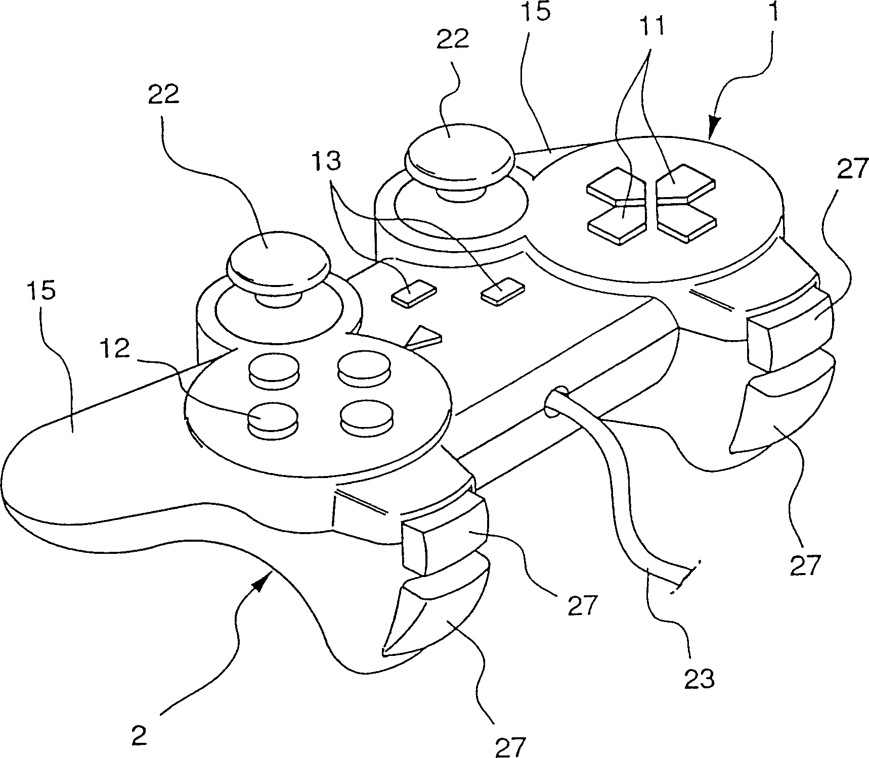
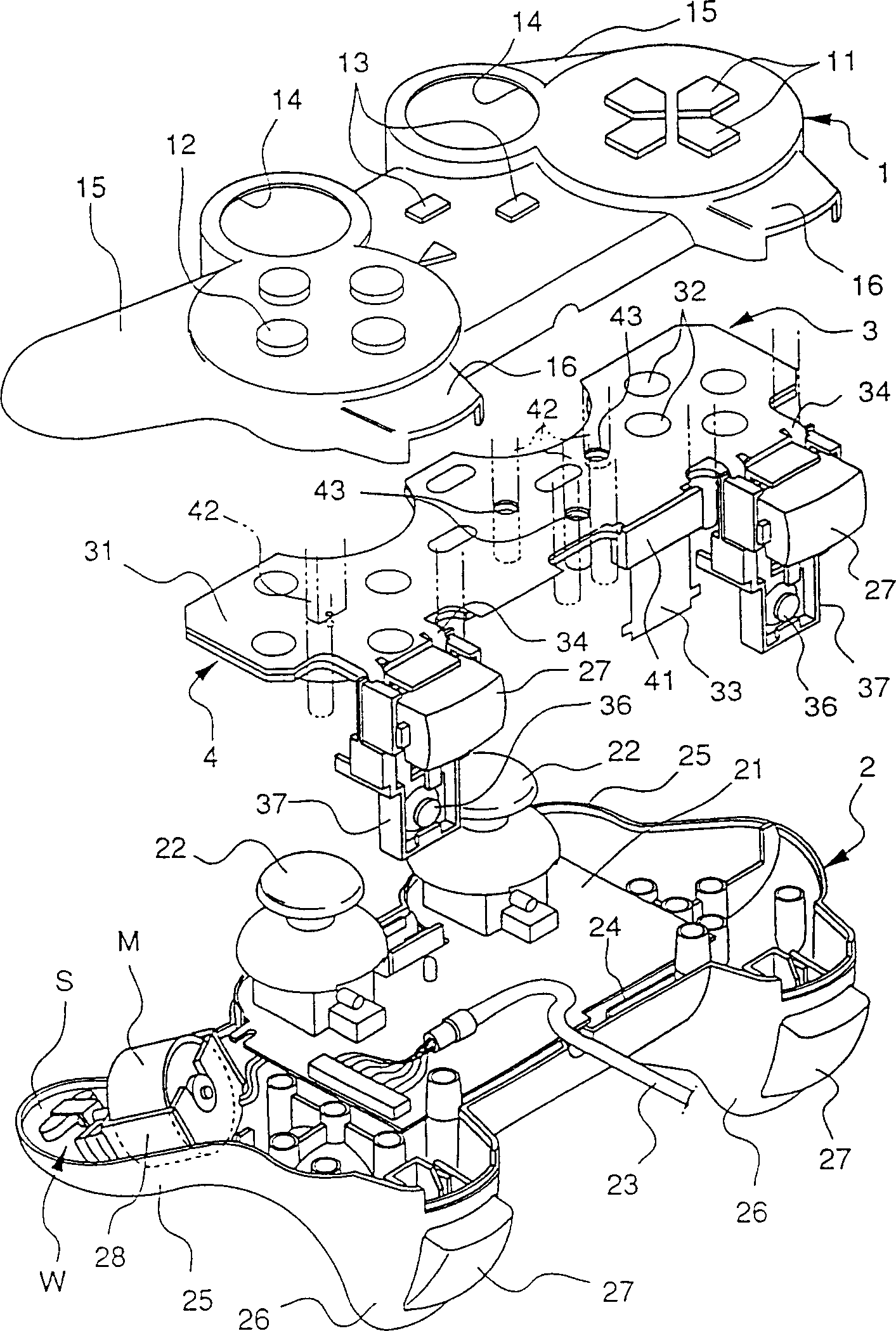
[0030] figure 1 and figure 2 Among them, 1 is the upper case (the first case part) constituting the upper side of the controller frame part, 2 is the lower case (the second case part) constituting the lower side of the frame part, and 3 is the The flexible substrate (having flexible diaphragm substrate) in the inner space that upper box body 1 and lower box body 2 constitutes, 4 is the plate (fixed part) that flexible substrate 3 is fixed on upper box body 1 inner surface.

[0031] Such as figure 1 As shown, on the top of the upper case body 1, a cross key (operator) 11 is provided on one end side, a key head (operator) 12 composed of four kinds of keys is provided on the other end side, and a cross key (operator) 12 is provided on the central part. Select key (operator) 13 . Holes 14 , 14 are formed at the rear (operator side) end of the upper surface, through which operation rods 22 , 22 to be described later pass and their heads protrude. Semicircular members 15 , 15 p...


PUM


Abstract

The present invention provided a vibration generator and input device for game equipment using the same, and it can reduce the number of the parts, can make a controller small in size and light in weight to reduce the cost and the kinds of the parts while improving the operation character of the controller, and will achieve a plurality of functions easily. Disclosed is an input device (controller) for inputting signals to a game apparatus using a computer. The input device includes a vibration generating machine (a vibration generating device), the vibration state of which can be set in correspondence with the frequency.

Description

technical field [0001] The present invention relates to an input device for a game machine and a vibration generating device used for the input device. In the input device for a game machine, the player uses an operation key, an operation button, or an operation lever to operate components such as an operation key, on a game machine screen of a computer, to It is possible to play an immersive game. Background technique [0002] In recent years, a lot of game software that can be pre-stored in the computer or input during the game has been developed. Correspondingly, game machines (hereinafter simply referred to as game machines) using computers are also rapidly popularized. Various operation parts such as operation keys, operation buttons, and joysticks allow the game to be played on the display screen. The software used in this game machine includes various types of software such as a scrolling display mode, a speed competition mode, a shooting mode, a fighting and dialogu...

Claims


Application Information

Patent Timeline
IPC IPC(8): B06B1/16A63F13/24A63F13/285
CPCA63F2300/1037A63F13/06B06B1/164Y10T74/18552A63F2300/1043A63F13/24A63F13/285B06B1/16
Inventor 相马正博
Owner ALPS ALPINE CO LTD
Learn More