Switch cabinet for electrical engineering

A technology of electrical engineering and switchgear, which is applied in the direction of switchgear components, horizontally isolated switchgear, cleaning methods and appliances, etc. Knot or hang the cabinet and other problems

Pending Publication Date: 2021-09-14
北京建企动力科技工程有限公司
View PDF1 Cites 0 Cited by
  • Summary
  • Abstract
  • Description
  • Claims
  • Application Information

AI Technical Summary

Problems solved by technology

[0004] However, in the prior art, the drawer cabinet is electrically connected to the cabinet body through the flexible wire harness fixed at the tail, and the folded flexible wire harness keeps the drawer cabinet in good electrical communication with the cabinet body when it is freely drawn, but the existing The flexible wire harness is usually composed of multiple loose single-strand wires. During t...

Method used


Image

  • Switch cabinet for electrical engineering
  • Switch cabinet for electrical engineering
  • Switch cabinet for electrical engineering

Examples


Embodiment 1

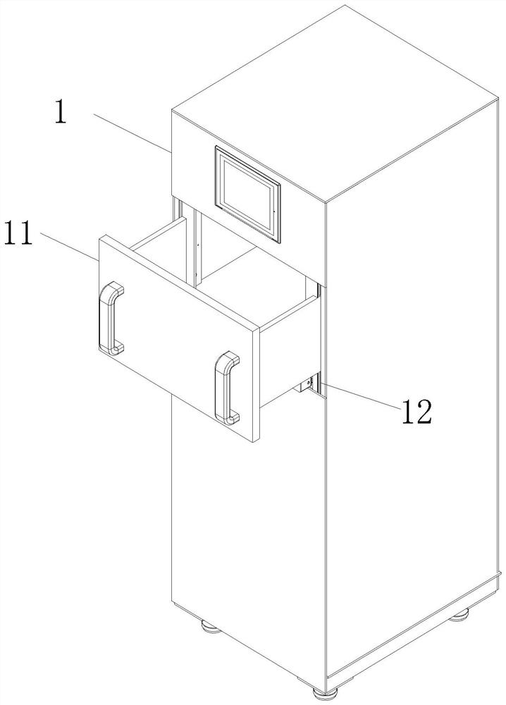
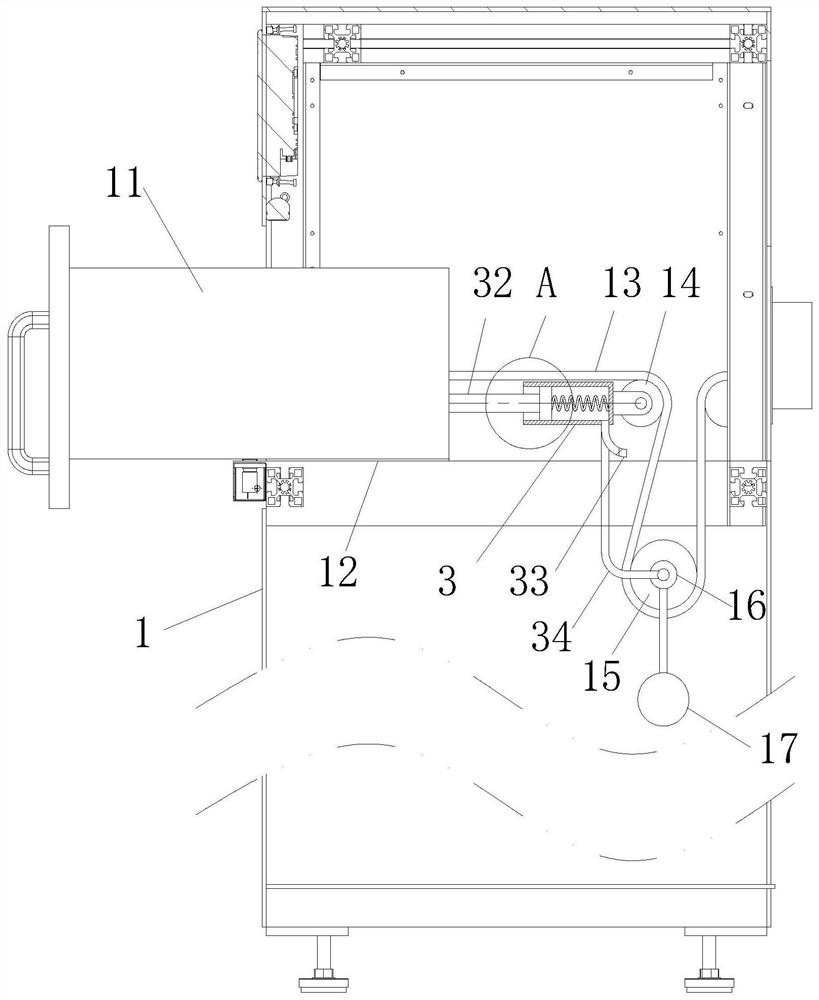
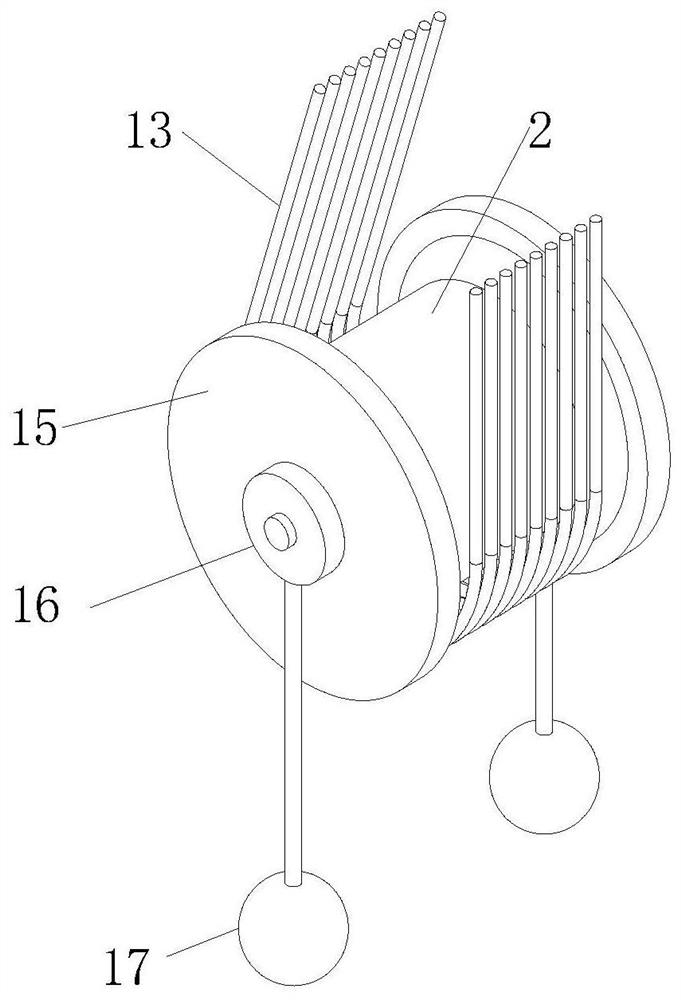
[0031] like Figure 1 to Figure 6 As shown, a switch cabinet for electrical engineering according to the present invention includes a cabinet body 1 and a drawer cabinet 11; The tail is connected with a set of flexible wire row 13, the wire row 13 is naturally drooped and folded and then electrically connected to the cabinet body 1, and the position corresponding to the wire row 13 in the cabinet body 1 is rotated and connected with a guide wheel 14, and the guide wheel 14 is placed on the wire Below the row 13; the guide wheel 14 is provided with a counterweight wheel 15 on the top of the conductor row 13 between the cabinets 1, and the counterweight wheel 15 is rollingly connected with the conductor row 13; Sleeve 16, shaft sleeve 16 is fixedly connected with counterweight ball 17 through pull rod; During work, the drawer cabinet 11 in the prior art is electrically connected with the cabinet body 1 through the flexible wire harness fixed at the tail, and the folded flexible ...

Embodiment 2

[0041] like Figure 7 As shown in Comparative Example 1, another embodiment of the present invention is: the side of the insertion rod 41 close to the inner wall of the No. The end inner wall is fixedly connected with a sponge ball 46, and the sponge ball 46 is soaked with lubricating oil; the side of the plunger 41 near the cam 42 is provided with an arc-shaped oil storage tank 47 at the corresponding position of the cam 42, and the oil storage tank 47 is close to the side of the cam 42. One side is sealed and connected with an elastic telescopic piece 48, and the oil storage tank 47 communicates with the sponge ball 46 through a pipeline; the cleaning efficiency of the insertion rod 41 to the No. Interstitial extrusion, the scraper 45 continuously squeezes and scrapes the inner wall of No. 1 hole 39, and at the same time, when the scraper 45 is squeezed, the sponge ball 46 overflows lubricating oil, increasing the lubrication of the inner wall of No. 1 hole 39, and reducing ...


PUM


Abstract

The invention belongs to the technical field of power equipment, and particularly relates to a switch cabinet for electrical engineering, which comprises a cabinet body and a drawer cabinet, the drawer cabinet is slidably connected to a sliding rail in an open groove in one side of the cabinet body, the tail of the drawer cabinet is connected with a group of flexible wire rows, the wire rows naturally droop and are folded to be electrically connected with the cabinet body, guide wheels are rotatably connected to the positions, corresponding to the wire rows, in the cabinet body, and the guide wheels are arranged below the wire rows. A counterweight wheel is arranged at the tops of the wire rows between the guide wheels and the cabinet body, and the counterweight wheel is in rolling connection with the wire rows; and shaft sleeves are rotationally connected to the two sides of the balance weight wheel and fixedly connected with balance weight balls through pull rods. The guide wheels are used for carding and supporting the wire rows, and the counter weight wheel and the counter weight ball are matched for downward constant pulling force on the wire rows, so that the wire rows are tidily and orderly bent and straightened during winding and unwinding, and knotting and winding between the wire rows are avoided.

Description

technical field [0001] The invention belongs to the technical field of electric equipment, in particular to a switch cabinet for electrical engineering. Background technique [0002] The main function of the slope switchgear is to switch, control and protect electrical equipment during the process of power generation, transmission, distribution and power conversion in the power system. The components in the switch cabinet are mainly composed of circuit breakers, disconnectors, load switches, operating mechanisms, transformers and various protection devices. [0003] There are also some technical solutions about injection molds in the prior art. For example, a Chinese patent with application number 202010807363.1 discloses a switch cabinet, which includes a cabinet body. The cabinet body is provided with an accommodation cavity, which can accommodate wiring device, the wiring device is provided with a first block and a second block, the first block and the second block are v...

Claims


Application Information

Patent Timeline
IPC IPC(8): H02B11/12H02B11/02H02B1/21B08B1/00B08B1/02
CPCH02B11/12H02B11/02H02B1/21B08B1/002B08B1/02
Inventor 高旭
Owner 北京建企动力科技工程有限公司
Why Eureka
Try Eureka