Hot-rolled H-shaped steel and production method thereof

A production method and technology for H-beams, applied in metal rolling, metal rolling, rolling mill control devices, etc., can solve the problems of flange surface wave or web surface wave defect, side bending, non-disclosure, etc., and meet product specifications A wide range of effects

Active Publication Date: 2021-09-17
MAANSHAN IRON & STEEL CO LTD
View PDF10 Cites 4 Cited by
  • Summary
  • Abstract
  • Description
  • Claims
  • Application Information

AI Technical Summary

Problems solved by technology

This patent has strict restrictions on the ratio of the thickness of the flanges on both sides of the hot-rolled H-shaped steel, and the difference between the thickness of the flange and the web. If the size exceeds the range, it will cause serious side bending during the rolling process, or obvious flange surface waves. Or web surface wave defects affect the actual use; in addition, this method can only produce H450*150 series specifications, for larger or smaller specifications, because the area ratio of flange and web is different from this specification, then this method not applicable
[0004] At present, there is no disclosed method in the prior art, which can produce hot-rolled H-beams of various specifications with unequal thicknesses on both sides of the flange

Method used


Image

  • Hot-rolled H-shaped steel and production method thereof
  • Hot-rolled H-shaped steel and production method thereof

Examples


Embodiment 1

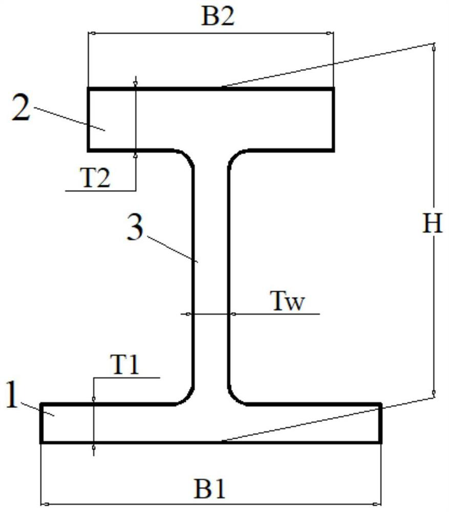
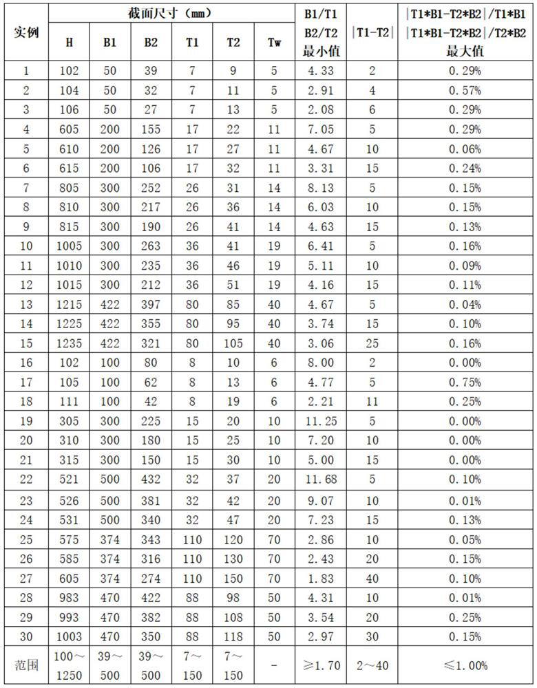
[0049] As shown in Table 1, the web height H is 102 mm, the width B1 of the first flange plate 1 is 50 mm, the width B2 of the second flange plate 2 is 39 mm, and the thickness T1 of the first flange plate 1 is 7 mm. The thickness T2 of the second flange plate 2 is 9mm, the web thickness Tw is 5mm, |T1-T2|=2mm, |T1*B1-T2*B2| / T1*B1 and |T1*B1-T2*B2| / The maximum value of both T2*B2 is 0.29.

Embodiment 2

[0051] As shown in Table 1, the web height H is 104 mm, the width B1 of the first flange plate 1 is 50 mm, the width B2 of the second flange plate 2 is 32 mm, and the thickness T1 of the first flange plate 1 is 7 mm. The thickness T2 of the second flange plate 2 is 11mm, the web thickness Tw is 5mm, |T1-T2|=2.91mm, |T1*B1-T2*B2| / T1*B1 and |T1*B1-T2*B2| / T2*B2 The maximum of the two is 0.57.

Embodiment 3

[0053] As shown in Table 1, the web height H is 106 mm, the width B1 of the first flange plate 1 is 50 mm, the width B2 of the second flange plate 2 is 27 mm, and the thickness T1 of the first flange plate 1 is 7 mm. The thickness T2 of the second flange plate 2 is 13mm, the web thickness Tw is 5mm, |T1-T2|=2.08mm, |T1*B1-T2*B2| / T1*B1 and |T1*B1-T2*B2| / T2*B2 The maximum of the two is 0.29.


PUM

PropertyMeasurementUnit
thicknessaaaaaaaaaa
thicknessaaaaaaaaaa

Abstract

The invention discloses hot-rolled H-shaped steel, which comprises a web plate, a first flange plate and a second flange plate; the difference value T1-T2 between the thickness value of the first flange plate and the thickness value of the second flange plate is larger than 0; the ratio of the area difference S1-S2 of the first flange plate and the second flange plate to the area S1 of the first flange plate is not larger than 1, or the ratio of the area difference S1-S2 of the first flange plate and the second flange plate to the area S2 of the second flange plate is not larger than 1. According to the hot-rolled H-shaped steel provided by the invention, the production requirement that the flanges on the two sides of various specifications are different in thickness can be met, meanwhile, lateral bending in the rolling process can be avoided, the metal second flow difference of the flanges on the two sides in the rolling process is controlled within a certain range, and therefore the hot-rolled H-shaped steel with the flanges on the two sides being different in thickness is stably produced. The invention further discloses a production method of the hot-rolled H-shaped steel.

Description

technical field [0001] The invention belongs to the technical field of H-shaped steel, in particular, the invention relates to a hot-rolled H-shaped steel and a production method thereof. Background technique [0002] At present, hot-rolled H-beams are all produced by universal rolling, and the rolled pieces are double-symmetrically rolled (in the height and width directions) in an "H" shape during the universal rolling stage. Among them, the upper and lower horizontal rolls roll and compress the web in the thickness direction, and the vertical rolls on both sides respectively roll and compress the flanges on both sides in the thickness direction. If the thickness or width of the flanges on both sides is not controlled during the rolling process, there will be a gap in the metal second flow of the flanges on both sides, resulting in different rolling extensions on both sides, and the rolled piece will inevitably appear side bending, which will affect the The second bite. I...

Claims


Application Information

Patent Timeline
Patent Type & Authority Applications(China)
IPC IPC(8): B21B1/088B21B1/46B21B37/00F16S3/00
CPCB21B1/088B21B1/463B21B37/00F16S3/00B21B2037/002B21B2201/06
Inventor 夏勐陈辉汪杰邢军黄琦彭林何军委沈千成丁朝晖彦井成吴保桥吴湄庄
Owner MAANSHAN IRON & STEEL CO LTD
Why Eureka
Try Eureka