Universal battery module welding tool pressing plate

A battery module and welding tooling technology, applied in welding equipment, auxiliary welding equipment, welding/cutting auxiliary equipment, etc. Increase the overall cost of production tooling and other issues to achieve the effect of improving overall production efficiency and production progress, scientific structure design, and saving processing time

Pending Publication Date: 2021-09-17
LISHEN (QINGDAO) NEW ENERGY CO LTD
0 Cites 0 Cited by

AI-Extracted Technical Summary

Problems solved by technology

[0004] However, the existing module welding tool press plate has poor compatibility. Usually, a module welding tool press plate can only be used for a battery module with a fixed number of cells and a fixed distance between cells (adjacent batteries in the battery module) The pole spacing on the top of the cell is fixed, and the structure is single) for compaction operation, and the compaction operation cannot be performed on various battery modules with different numbers of cel...

Abstract

The invention discloses a universal battery module welding tool pressing plate. The universal battery module welding tool pressing plate comprises a fixing plate (1), wherein a limiting slot hole (7) is formed in each of the front side, the rear side and the longitudinal middle position of the fixing plate (1); a plurality of sliding pressing block assemblies (4) are arranged under the fixing plate (1); a battery module (10) needing to be welded and pressed is arranged under the fixing plate (1), and the battery module (10) comprises a plurality of square battery cells (100) which are longitudinally distributed; and the plurality of sliding pressing block assemblies (4) are separately and correspondingly positioned right above the plurality of battery cells (100). The universal battery module welding tool pressing plate is scientific in structural design, the problems that a welding tool pressing plate is single in structure and poor in compatibility can be solved, various battery modules with different battery cell numbers and different battery cell intervals can be compacted, and the overall cost of tool production is remarkably reduced.

Application Domain

Technology Topic

Image

  • Universal battery module welding tool pressing plate
  • Universal battery module welding tool pressing plate
  • Universal battery module welding tool pressing plate

Examples

  • Experimental program(1)

Example Embodiment

[0043] In order to make the technical means realized by the present invention easier to understand, the present application will be further described in detail below in conjunction with the accompanying drawings and embodiments. It should be understood that the specific embodiments described here are only used to explain the related application, not to limit the application. In addition, it should be noted that, for ease of description, only parts relevant to the present application are shown in the drawings.
[0044] It should be noted that, in the case of no conflict, the embodiments in the present application and the features in the embodiments can be combined with each other. The present application will be described in detail below with reference to the accompanying drawings and embodiments.
[0045] It should be noted that in the description of this application, the terms "center", "upper", "lower", "left", "right", "vertical", "horizontal", "inner", "outer", etc. The terms of the indicated direction or positional relationship are based on the direction or positional relationship shown in the drawings, which are only for the convenience of description, and do not indicate or imply that the device or element must have a specific orientation, be constructed and operated in a specific orientation , and therefore cannot be construed as limiting the application.
[0046] In addition, it should be noted that in the description of the present application, unless otherwise specified and limited, the term "installation" should be understood in a broad sense, for example, it may be a fixed installation or a detachable installation.
[0047] Those skilled in the art can understand the specific meanings of the above terms in this application according to specific situations.
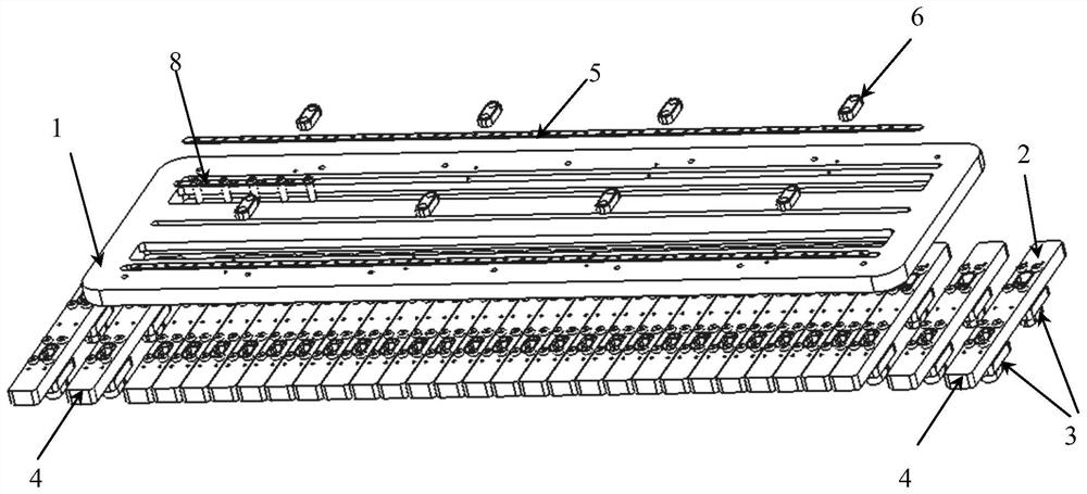
[0048] see Figure 1 to Figure 5 , the present invention provides a general-purpose battery module welding tool press plate, including a horizontally distributed fixed plate 1;
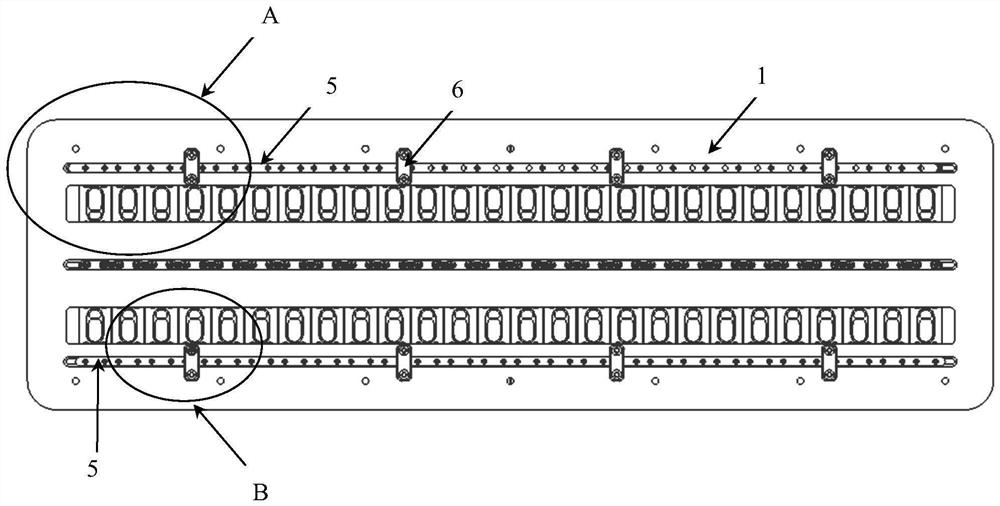
[0049] Wherein, the front and rear sides of the fixed plate 1 and the longitudinal middle position are respectively provided with a horizontally distributed long hole 7 for limiting;
[0050] Directly below the fixed plate 1, there are a plurality of longitudinally distributed sliding pressure block assemblies 4 capable of adjusting the fixed position on the limiting long hole 7;
[0051] Wherein, each sliding briquetting block assembly 4 includes a briquetting block connecting plate 2 and two briquetting blocks 3;
[0052] The front and rear ends of the longitudinally distributed briquetting block connecting plate 2 are respectively opened and fixed with a briquetting block 3;
[0053] A pair of screw holes are respectively provided at the top, front and rear ends and the longitudinal middle of each pressing block connecting plate 2 at positions corresponding to each limiting long hole 7;
[0054] Each pair of screw holes is threadedly connected with a pair of fastening screws 8;
[0055] Each pair of fastening screws 8 vertically passes through the adjacent limiting long holes 7, and the head of each fastening screw 8 is located in the limiting long holes 7;
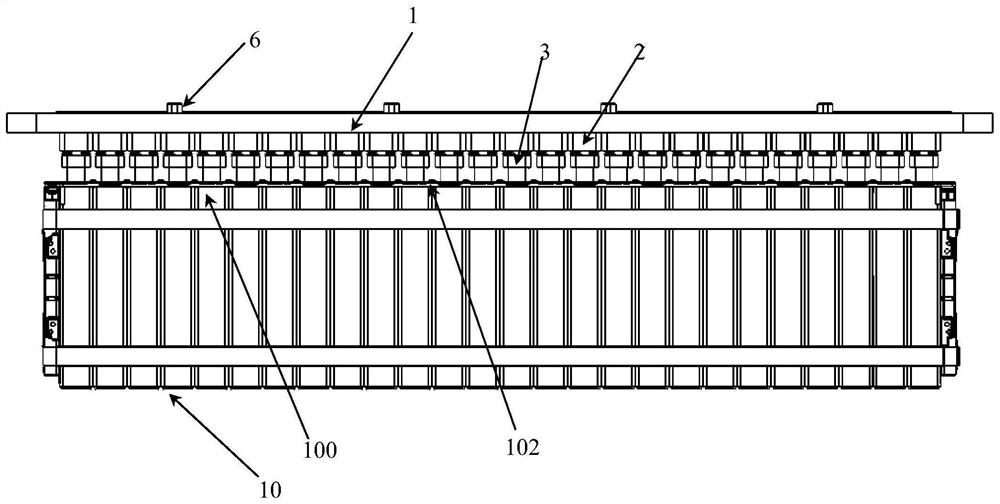
[0056] Wherein, directly below the fixing plate 1, a battery module 10 that needs to be welded and pressed is arranged;
[0057] The battery module 10 includes a plurality of vertically distributed square cells 100;
[0058] A plurality of sliding pressing block assemblies 4 are respectively located directly above the plurality of battery cells 100;
[0059] Wherein, the bottoms of the two briquetting blocks 3 of each sliding briquetting block assembly 4 are used for compacting the pole on the top of the cell directly below and the bus bar on the top surface of the pole;
[0060] Wherein, the front and rear sides of the fixed plate 1 respectively have a transversely distributed welding slot 9;
[0061] Two welding long holes 9 are respectively located in the inner direction of the two limiting long holes 7 on the front and rear sides of the fixed plate 1;
[0062] The tops of the two briquetting blocks 3 of each sliding briquetting block assembly 4 are respectively located directly below the two welding elongated holes 9;
[0063] Each pressing block 3 has a first welding operation through hole 31 and a second welding operation through hole 32 vertically penetrating and spaced apart from each other.
[0064] It should be noted that, for the present invention, after the specific position of the fastening screw 8 on the limit slot 7 can be moved laterally left and right, it can be tightened and fixed, so that the lateral specific position of each sliding pressing block assembly 4 can be adjusted. Each sliding pressing block assembly 4 can be adjusted to a specific fixed position on the limiting long hole 7, so that multiple sliding pressing block assemblies 4 can press multiple cells in a battery module with different cell pitches. practical operation.
[0065] In the present invention, in terms of specific implementation, the position-limiting long hole 7 includes an upper hole and a lower hole that communicate with each other;
[0066] the upper bore slot, which sits on top of the lower bore slot;
[0067] The longitudinal width of the lower hole is smaller than the longitudinal width of the upper hole.
[0068] It should be noted that the head of the fastening screw is located at the top of the lower hole groove.
[0069] In the present invention, in terms of specific implementation, the number of sliding pressing block assemblies 4 is greater than or equal to the number of battery cells 100 included in the battery module 10 .
[0070] In the present invention, in terms of specific implementation, in order to improve the connection efficiency between the fastening screws 8 on the plurality of sliding pressing block assemblies 4 and the limiting long holes 7, and to ensure that the plurality of sliding pressing block assemblies 4 and a battery module 10 The multiple battery cells 100 in the battery are crimped up and down correspondingly, and the general-purpose battery module welding tool press plate included in the present invention also includes two auxiliary installation strips 5;
[0071] Each auxiliary installation strip 5 is set correspondingly to the two limiting long holes 7 located on the front and rear sides of the fixing plate 1, and is located in the limiting long holes 7;
[0072] On each auxiliary installation bar 5, there are many pairs of fastening screw through holes 50;
[0073] Each pair of fastening screw through holes 50 are used to pass through a pair of fastening screws 8;
[0074] A plurality of pairs of fastening screw through holes 50 on each auxiliary mounting strip 5 are set up and down in direct correspondence with the plurality of battery cells 100 in the battery module 10 .
[0075] It should be noted that, for the present invention, the spacing between multiple pairs of fastening screw through-holes 50 on each auxiliary mounting strip 5, and according to the order of arrangement from left to right, is respectively consistent with that of multiple pairs of a battery module 10. The spacing between the batteries 100 is the same in one-to-one correspondence.
[0076] For the present invention, for a variety of battery modules with different numbers of cells and different cell spacings, corresponding auxiliary installation strips can be prefabricated, so that the sliding pressing block assembly 4 in the pressing plate of the present invention can meet the requirements conveniently and quickly. The pressing operation requirements of various battery modules facilitate the type change operation of the present invention.
[0077] In terms of specific implementation, the shape and size of each auxiliary installation strip 5 correspond to the shape and size of the upper slot in the limiting slot 7 .
[0078] In the present invention, in terms of specific implementation, directly above each auxiliary installation strip 5, a plurality of longitudinally distributed compression strips 6 are arranged at equal intervals;
[0079] The front and rear ends of each pressing bar 6 are fixedly connected to the top of the fixing plate 1 by screws respectively.
[0080] In the present invention, in terms of specific implementation, the first welding operation through hole 31 and the second welding operation through hole 32 on each pressing block 3 are respectively located directly above the sampling nickel sheet 103 and the pole 101 on the top of the battery cell 100 ;
[0081] The pole 101 on the top of the battery cell 100 is located in the pole receiving hole reserved on the horizontally distributed busbar 102 .
[0082] It should be noted that the function of the sampling nickel sheet 103 is to collect the voltage and temperature data of the cell; the sampling nickel sheet 103 is welded to the bus bar 102 above the cell; the sampling nickel sheet 103 can be a temperature sampling nickel sheet Or voltage sampling nickel sheet.
[0083] see figure 2 as shown, figure 2 The battery module 10 is a 26-series module. By applying the present invention, 26 sets of slider pressing block assemblies 4 with different spacings can be installed on the fixing plate according to the number of batteries in the battery module 10 and the spacing of different batteries. It can be guaranteed that during welding, the poles, busbars and sampling nickel sheets at each pole point of the cell are compacted and the welding area is exposed.
[0084] In summary, compared with the prior art, the present invention provides a general-purpose battery module welding tool press plate, which has a scientific The group performs compaction operation, which significantly reduces the overall cost of production tooling, which has great practical significance.
[0085] In addition, through the application of the present invention, there is no need to additionally produce a plurality of module welding tooling press plates, which is beneficial to saving the processing time of the production tooling and improving the overall production efficiency and production progress of the battery module.
[0086] The above is only a preferred embodiment of the present invention, it should be pointed out that, for those of ordinary skill in the art, without departing from the principle of the present invention, some improvements and modifications can also be made, and these improvements and modifications can also be made. It should be regarded as the protection scope of the present invention.

PUM

no PUM

Description & Claims & Application Information

We can also present the details of the Description, Claims and Application information to help users get a comprehensive understanding of the technical details of the patent, such as background art, summary of invention, brief description of drawings, description of embodiments, and other original content. On the other hand, users can also determine the specific scope of protection of the technology through the list of claims; as well as understand the changes in the life cycle of the technology with the presentation of the patent timeline. Login to view more.

Similar technology patents

Classification and recommendation of technical efficacy words

  • Structural Design Science
  • Single solution

Self-refrigerating or self-heating beverage bottle

InactiveCN105947414AThe device is safe and reliableStructural Design ScienceContainers for heating foodShock-sensitive articlesPhysicsChemistry
Owner:东营市一大早乳业有限公司

Novel combined dust removal device for laser welding of power battery module

PendingCN112427806AStructural Design ScienceReduce smoke and dust pollutionLaser beam welding apparatusLaser solderingSlag (welding)
Owner:WUHAN LISHEN POWER CELL SYST TECH CO LTD +1

Electronic equipment

ActiveCN110426946AImprove dynamismSingle solutionSide-by-side/stacked arrangementsElectronic time-piece structural detailsElectrical and Electronics engineeringElectronic equipment
Owner:VIVO MOBILE COMM CO LTD

Integral type air energy heat pump device

ActiveCN110195942ASingle solutionHeat pumpsPipingEngineering
Owner:山东小鸭集团小家电有限公司

Wrist ball rotating speed device

InactiveCN107899200ASingle solutionGymnastic exercisingBall sportsHandsetWrist
Owner:YANCHENG JIAHUA PLASTIC PROD CO LTD
Why Eureka
Try Eureka