Control method and device of grinding and filing tool, electronic equipment and storage medium
A control method and tool technology, applied in the field of control methods, devices, electronic equipment and storage media of grinding tools, capable of solving problems such as lack of grinding tools
- Summary
- Abstract
- Description
- Claims
- Application Information
AI Technical Summary
Problems solved by technology
Method used
Image

Examples
Embodiment 1
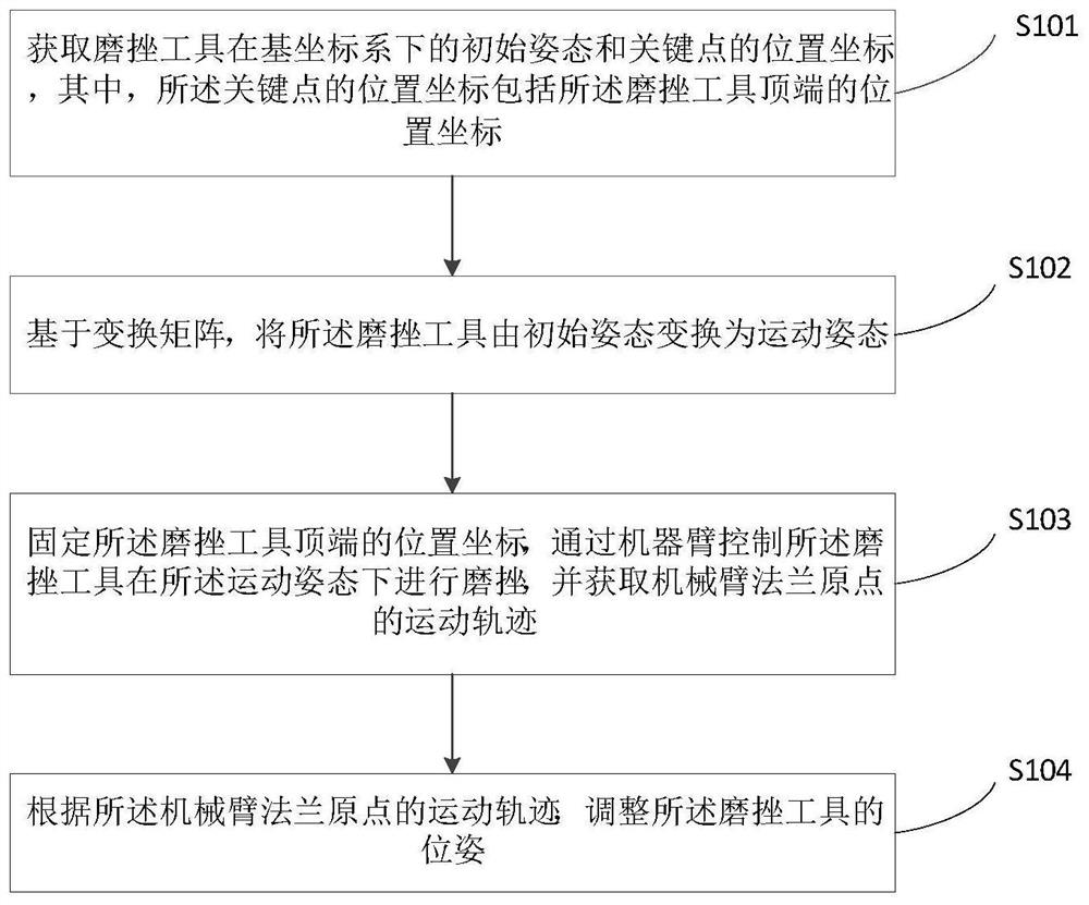
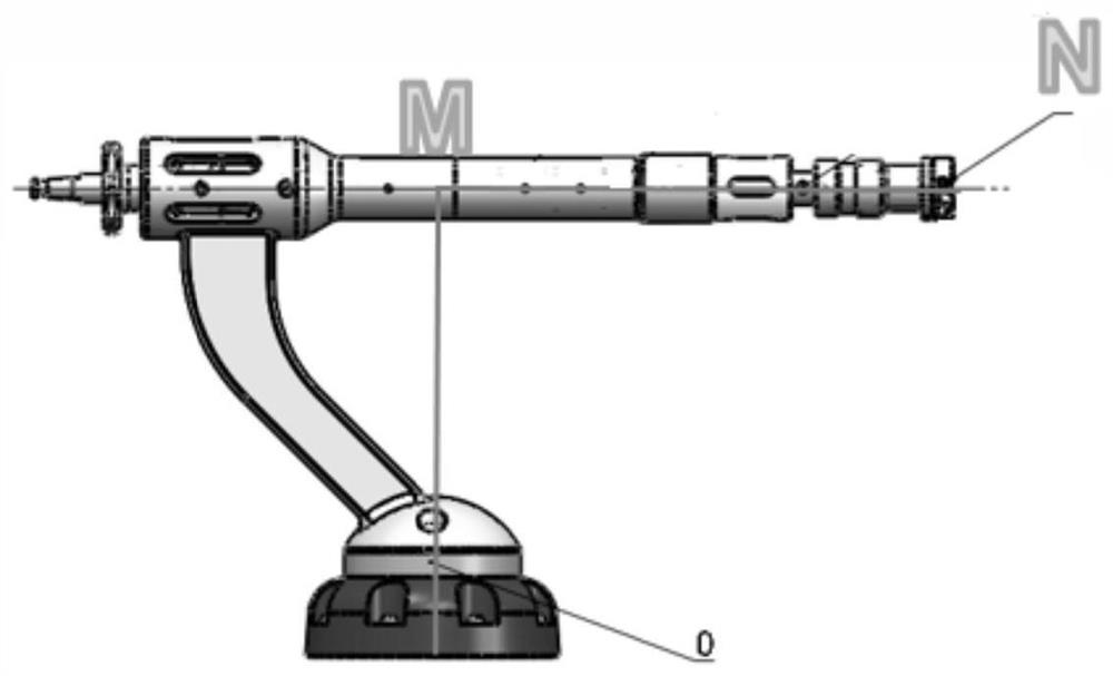
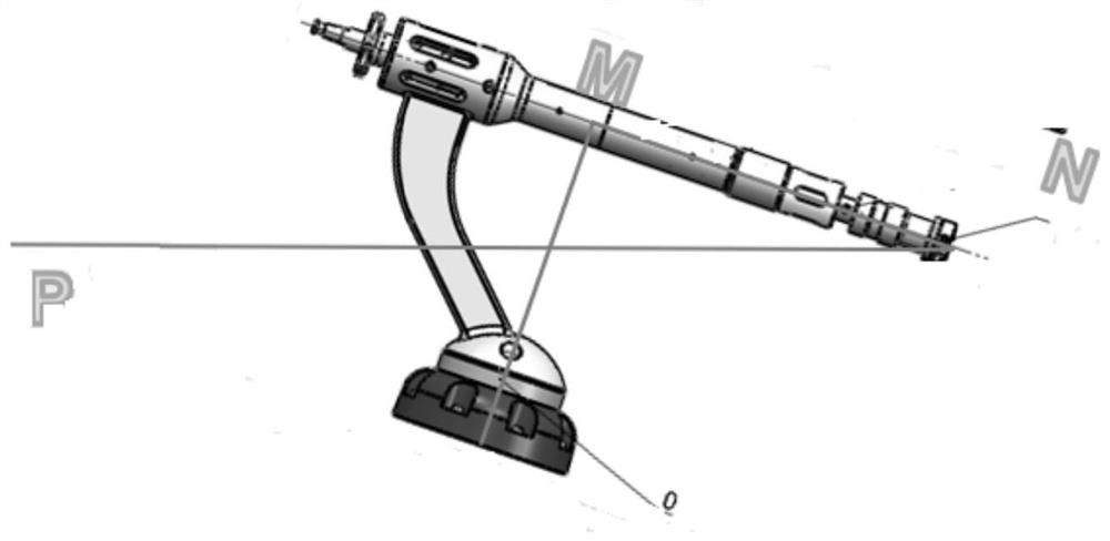
[0028] Embodiment 1 of the present invention provides a control method for a grinding tool, figure 1 It is a schematic flow chart of the grinding tool control method in Embodiment 1 of the present invention. figure 2 is a schematic diagram of the initial attitude during the motion of the frustrating tool, image 3 It is a schematic diagram of the movement posture during the movement of the frustrating tool, such as figure 1 As shown, the grinding tool control method of Embodiment 1 of the present invention includes the following steps:
[0029] S101: Obtain the initial posture of the frustrating tool in the base coordinate system and the position coordinates of the key points, wherein the position coordinates of the key points include the position coordinates of the tip of the frustrating tool.
[0030] In Embodiment 1 of the present invention, a ball-shaped grinding tool is installed at the top position N of the grinding tool, and the center of the ball is located at point...
Embodiment 2
[0050] Corresponding to Embodiment 1 of the present invention, Embodiment 2 of the present invention provides a control device for a grinding tool. Figure 5 It is a schematic structural diagram of a grinding tool control device in Embodiment 2 of the present invention, as figure 2 As shown, the frustrating tool control device according to Embodiment 2 of the present invention includes an acquisition module 20 , an attitude transformation module 22 and a frustrating module 24 .
[0051] Specifically, the acquisition module 20 is configured to acquire the initial posture of the frustrating tool in the base coordinate system and the position coordinates of the key points, wherein the position coordinates of the key points include the position coordinates of the top of the frustrating tool;
[0052] The posture transformation module 22 is used to transform the frustrating tool from an initial posture to a motion posture based on a transformation matrix;
[0053] The frustrating...
Embodiment 3
[0055] An embodiment of the present invention also provides an electronic device, which may include a processor and a memory, where the processor and the memory may be connected through a bus or in other ways.
[0056] The processor may be a central processing unit (Central Processing Unit, CPU). The processor can also be other general-purpose processors, digital signal processors (Digital Signal Processor, DSP), application-specific integrated circuits (Application Specific Integrated Circuit, ASIC), field-programmable gate array (Field-Programmable Gate Array, FPGA) or other Chips such as programmable logic devices, discrete gate or transistor logic devices, discrete hardware components, or combinations of the above-mentioned types of chips.
[0057] As a non-transitory computer-readable storage medium, the memory can be used to store non-transitory software programs, non-transitory computer-executable programs and modules, such as program instructions / modules corresponding ...
PUM
 Abstract
Description
Claims
Application Information
 - R&D
- Intellectual Property
- Life Sciences
- Materials
- Tech Scout
- Unparalleled Data Quality
- Higher Quality Content
- 60% Fewer Hallucinations
Browse by: Latest US Patents, China's latest patents, Technical Efficacy Thesaurus, Application Domain, Technology Topic, Popular Technical Reports.
© 2025 PatSnap. All rights reserved.Legal|Privacy policy|Modern Slavery Act Transparency Statement|Sitemap|About US| Contact US: help@patsnap.com