Mounting device for motor assembly

A technology for installing equipment and pressing molds, which is used in electromechanical devices, manufacturing motor generators, electrical components, etc., can solve the problem that the end cover is not easy to fit on the rotating shaft, and achieve the effect of improving assembly efficiency

Active Publication Date: 2021-09-17
SHANGHAI JIANDONG TECH CO LTD
View PDF6 Cites 0 Cited by
  • Summary
  • Abstract
  • Description
  • Claims
  • Application Information

AI Technical Summary

Problems solved by technology

[0005] In order to improve the problem that the end cover is not easy to be placed on the shaft when the operator assembles the micro motor, the application provides a mounting device for motor assembly

Method used


Image

  • Mounting device for motor assembly
  • Mounting device for motor assembly
  • Mounting device for motor assembly

Examples


Embodiment Construction

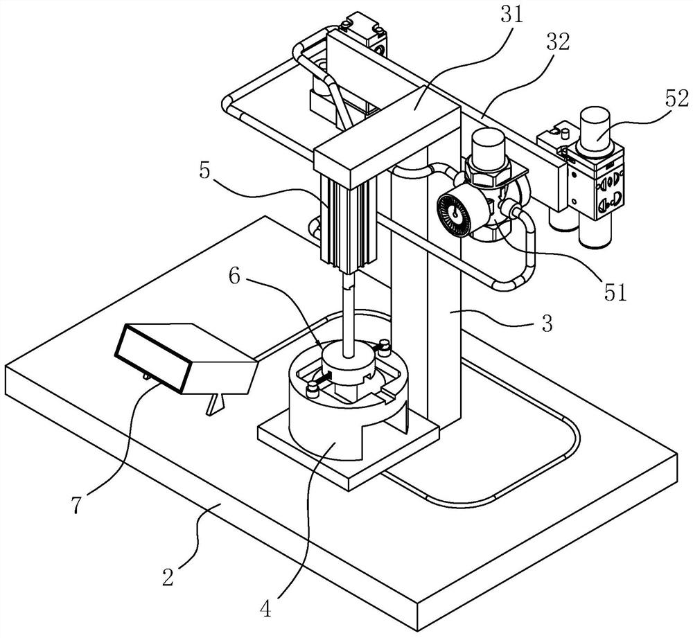
[0038] The following is attached Figure 1-8 The application is described in further detail.

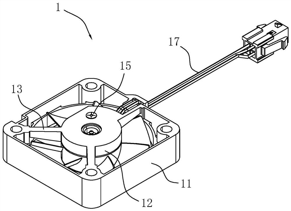
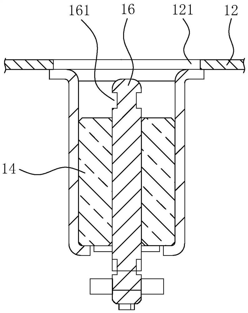
[0039] The embodiment of the present application discloses an installation device for motor assembly. refer to image 3 , the installation equipment for motor assembly includes a base 2 and a bracket 3, a mold base 4 is fixed on the base 2, a die 6 is installed on the support 3 above the die base 4 and the power to drive the die 6 to move close to or away from the die base 4 Part 5, a pressure sensor is installed at the bottom of the mold base 4, and a display 7 is connected to the stress sensor. Place the micro motor 1 on the mold base 4, place the end cap 15 on the installation port 121 of the inner casing 12, then start the power part 5 to drive the die 6 to move to the die base 4, and the die 6 applies the end cap 15 The pressure causes the end cap 15 to be sleeved on the rotating shaft 16, and the value measured by the pressure sensor can be displayed on the display 7 at the ...


PUM


Abstract

The invention relates to a mounting device for motor assembly, and relates to the technical field of motor production equipment, the mounting device comprises a base and a support, the base is fixedly provided with a die holder, and the die holder is provided with a positioning groove for placing a motor; a pressing die and a power piece are installed on the support, the pressing die is located over the positioning groove, the power piece can drive the pressing die to move close to the positioning groove, the pressing die is provided with a pressing column used for applying pressure to the end cover of the motor, and the end of the pressing column is provided with a receding hole allowing the end of a rotating shaft of the motor to stretch into. The mounting device has the advantage that a miniature motor shaft cover can be efficiently and stably assembled.

Description

technical field [0001] The present application relates to the technical field of motor production equipment, in particular to an installation device for motor assembly. Background technique [0002] A micro motor is a motor with a small volume and capacity. It generally has special requirements for use, performance and environmental conditions, so it is also called a micro special motor. Micro motors are currently used in various fields. Micro motors generally include stators, rotors, armature windings, brushes and other components, but are more compact than ordinary motors. [0003] Such as figure 1 with figure 2 As shown, it is a micro motor 1, the micro motor 1 includes an outer casing 11 and an inner casing 12, a rotor 14 is installed in the inner casing 12, and a rotating shaft 16 is coaxially inserted into the rotor 14; the outer casing 11 and the inner casing 12 It is fixed by connecting ribs 13, there are three connecting ribs 13 here, the inner housing 12 is pr...

Claims


Application Information

Patent Timeline
IPC IPC(8): H02K15/14
CPCH02K15/14
Inventor 程辰龚纯
Owner SHANGHAI JIANDONG TECH CO LTD
Why Eureka
Try Eureka