Simple mop

A mop and simple technology, applied in the field of mops, can solve the problems of complicated use methods, cost of mop materials, and reduced utilization rate, etc., and achieve the effects of high work efficiency, increased work efficiency, and low manufacturing cost.

Inactive Publication Date: 2021-09-21
武义县三玲清洁用品厂
View PDF0 Cites 0 Cited by
  • Summary
  • Abstract
  • Description
  • Claims
  • Application Information

AI Technical Summary

Problems solved by technology

[0003] The purpose of the present invention is to aim at the defects of the prior art, and provide a simple mop with simple structure, few materials, convenient, efficient and hygienic use, so as to deal with the current problems of mop materials and materials, high price, and complicated use methods. For example, most of the popular collodion cleaners are covered by the collodion itself and cannot touch the ground, causing waste and reducing the utilization rate.
Many mops look good but are not practical

Method used


Image

  • Simple mop
  • Simple mop

Examples


Embodiment 1

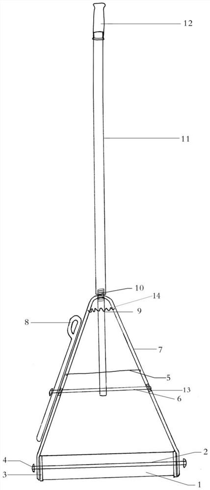
[0024] Such as figure 1 As shown, this example discloses a simple mop, which includes a mop rod 11, a mop rod bracket and a mop head connected in sequence. The upper end of the mop rod 11 is detachably connected to the cap head 12 of the mop rod, and the lower end is connected with the upper end of the mop rod support through a fastener 10; Drawbar 5, the upper end of the inverted V-shaped splint 7 is connected to the mop rod 11, and the two lower ends of the inverted V-shaped splint 7 are respectively sleeved on the horizontal axis 2 at both ends of the cleaning body 1, and can be placed on the horizontal axis 2 Sliding; the left and right sides of the inverted V-shaped splint 7 are respectively provided with a mounting hole 13 for the cross bar 6 to pass through. Shape splint 7 both sides make it extrude inwardly, loosen wrench 8 then inverted V-shaped splint 7 both sides restore to original state.

[0025] The left side of the cross bar 6 passes through the installation h...

Embodiment 2

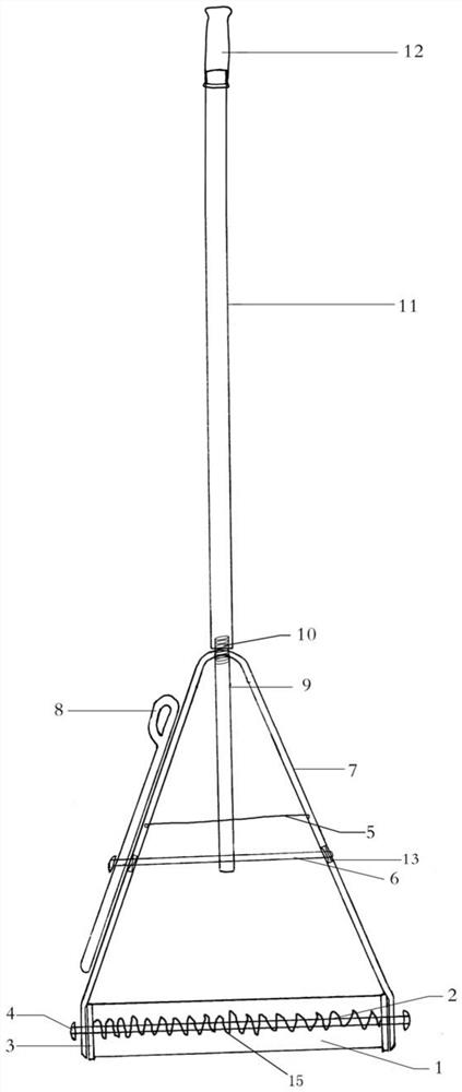
[0032] Different from Embodiment 1, the mop of this embodiment also includes a second spring 15, and the two ends of the second spring 15 are fixed to the two ends of the cleaning body 1, as figure 2 shown. Specifically, the two ends of the second spring 15 can be fixed directly with the two ends of the cleaning body, or can be fixed on the pressing pieces 3 at the two ends of the cleaning body. The second spring 15 can be sleeved on the horizontal shaft 2 , or installed between the horizontal shaft 2 and the cleaning body 1 .

[0033] Utilizing the elastic recovery force of the second spring, after the cleaning body made of sponge and other materials is compressed and squeezed out of water, when the inverted V-shaped splint is released, the cleaning body can automatically return to the unfolded state.


PUM


Abstract

The invention discloses a simple mop, which comprises a mop rod, a mop rod bracket and a mop head which are sequentially connected, wherein the mop head comprises a transverse shaft and a cleaning body arranged on the transverse shaft in a sleeving mode, limiting parts are arranged at the two ends of the transverse shaft, the mop rod bracket comprises an inverted-V-shaped clamping plate, the upper end of the inverted-V-shaped clamping plate is connected with the mop rod, and the two lower ends of the inverted-V-shaped clamping plate are arranged on the transverse shafts at the two ends of the cleaning body in a sleeving mode respectively and can slide on the transverse shaft.

Description

technical field [0001] The invention belongs to the technical field of mops, and in particular relates to a simple mop. Background technique [0002] The mops used in households and public places now have complex structures and various styles: good mops, scraping buckets, flat, round, inline, and detachable mops of various structures emerge in endlessly. These mops not only have different structures, but also have a variety of mop materials, such as collodion, sponge, cloth strips, gauze strips and the like. But above-mentioned mop all is to be made up of the cleaning body that is used for contacting with the ground, cleaning body firmware, mop bar three big blocks, or add special-purpose mop barrel four big blocks and form. Among them, there are also various types of firmware for the cleaning parts, such as two discs clamping the cleaning body, screws and nuts for fastening, and connecting parts connected with the mop rod, and the mop rod is divided into a main rod, a seco...

Claims


Application Information

Patent Timeline
Patent Type & Authority Applications(China)
IPC IPC(8): A47L13/14A47L13/20A47L13/24A47L13/42
CPCA47L13/14A47L13/20A47L13/24A47L13/42
Inventor 许刚许红峰
Owner 武义县三玲清洁用品厂
Why Eureka
Try Eureka