
Sputtering equipment and method capable of adjusting film stress

A technology of sputtering equipment and thin film stress, which is applied in the direction of sputtering plating, ion implantation plating, metal material coating process, etc., can solve problems such as difficulty in ensuring the uniformity of thin film stress, achieve simple and easy adjustment process, improve Thickness uniformity and effect of securing stability

Active Publication Date: 2021-09-21
BETONE TECH SUZHOU INC
View PDF6 Cites 1 Cited by
  • Summary
  • Abstract
  • Description
  • Claims
  • Application Information

AI Technical Summary

Problems solved by technology

[0003] In view of the above-mentioned shortcoming of the prior art, the object of the present invention is to provide a kind of sputtering equipment and method that can adjust film stress, be used for solving the problems in depositing film in the prior art, especially deposit such as metal nitrogen such as aluminum nitride It is difficult to ensure the uniformity of the stress of the film when using the compound film.

Method used


Image

  • Sputtering equipment and method capable of adjusting film stress
  • Sputtering equipment and method capable of adjusting film stress
  • Sputtering equipment and method capable of adjusting film stress

Examples


Embodiment Construction

[0024] Embodiments of the present invention are described below through specific examples, and those skilled in the art can easily understand other advantages and effects of the present invention from the content disclosed in this specification. The present invention can also be implemented or applied through other different specific implementation modes, and various modifications or changes can be made to the details in this specification based on different viewpoints and applications without departing from the spirit of the present invention. For example, when describing the embodiments of the present invention in detail, for the convenience of explanation, the cross-sectional view showing the device structure will not be partially enlarged according to the general scale, and the schematic diagram is only an example, which should not limit the protection scope of the present invention. In addition, the three-dimensional space dimensions of length, width and depth should be in...


PUM


Abstract

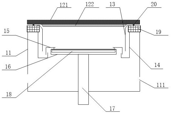
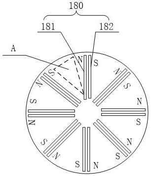
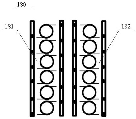
The invention provides sputtering equipment and method capable of adjusting film stress. The equipment comprises a cavity, a magnetron sputtering device, a baffle, a wafer pressing ring, a base and an electromagnetic coil module; one end of the wafer pressing ring is adjacent to the baffle, and the other end of the wafer pressing ring extends above the edge of the base; the base is connected with a grid bias power supply; the electromagnetic coil module is located in the base and / or between the wafer pressing ring and the base and comprises a plurality of electromagnetic coil sets, each electromagnetic coil set comprises an N-pole electromagnet and an S-pole electromagnet, the N-pole electromagnet in the single electromagnetic coil set is adjacently arranged on the left side of the corresponding S-pole electromagnet, and the N-pole magnetic pole face of each N-pole electromagnet and the S-pole magnetic pole face of each S-pole electromagnet face upwards or downwards at the same time; and in the sputtering process, the plurality of electromagnetic coil sets are divided into a plurality of power-on units, the plurality of power-on units are sequentially and alternately powered on and powered off in the clockwise or anticlockwise direction, so that a film is deposited on the surface of a substrate, and the film stress is adjusted. According to the sputtering equipment and the method capable of adjusting the film stress, and the film thickness and stress distribution uniformity can be improved.

Description

technical field [0001] The invention relates to the technical field of semiconductors, in particular to thin film deposition equipment, in particular to a sputtering equipment and method capable of adjusting thin film stress. Background technique [0002] During the fabrication of semiconductor devices, the stress of the deposited film is a problem that must be paid attention to. If the stress of the film cannot be controlled within a reasonable range, it will cause cracks in the film, and even lead to defects such as shedding in severe cases, resulting in shortened service life of the device. Therefore, the device has very high requirements on the uniformity of the film, especially the stress uniformity and crystal structure consistency of the metal nitride film, such as the aluminum nitride film. At present, the most difficult thing in stress control is to ensure stress uniformity. Using the aluminum nitride film deposited by the mainstream equipment on the market, the st...

Claims


Application Information

Patent Timeline
Patent Type & Authority Applications(China)
IPC IPC(8): C23C14/35C23C14/54C23C14/06
CPCC23C14/35C23C14/54C23C14/0641C23C14/0036
Inventor 潘钱森周云宋维聪
Owner BETONE TECH SUZHOU INC
Learn More