Autonomous positioning device and positioning method based on laser radar imaging

A lidar imaging and autonomous positioning technology, applied in the field of positioning and navigation, can solve the problems of wrong way, delay in transportation tasks, and easy loss of direction by drivers, and achieve the effect of ensuring reliability and real-time performance.

Pending Publication Date: 2021-09-21
INST OF APPLIED ELECTRONICS CHINA ACAD OF ENG PHYSICS
View PDF0 Cites 6 Cited by
  • Summary
  • Abstract
  • Description
  • Claims
  • Application Information

AI Technical Summary

Problems solved by technology

When the transport vehicle is in a harsh environment where satellite signals and radio signals are seriously interfered, such as at night, in dense fog or heavy rain, or even in a harsh environment without satellite positioning signals and radio positioning signals, the driver of the transport vehicle is likely to get lost and lead to the wrong way. Cause problems such as not being able to arrive at the destination on time, and the transportation task is delayed or even failed. Therefore, it is necessary to carry out independent positioning of the transportation vehicle without support

Method used


Image

  • Autonomous positioning device and positioning method based on laser radar imaging
  • Autonomous positioning device and positioning method based on laser radar imaging

Examples


Embodiment 1

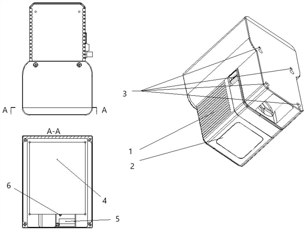
[0032] Such as figure 1 As shown, an autonomous positioning device based on laser radar imaging includes a housing, and the housing is provided with an imaging laser radar 1, a control memory 4 and an inertial measurement unit 5, and the imaging laser radar 1 and the inertial measurement unit 5 are respectively It communicates with the control memory 4, and the housing is installed on the corresponding bracket of the vehicle through the positioning hole 20.

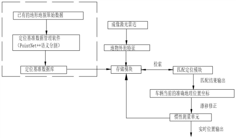
[0033] The control memory 4 is provided with a clock chip 6, a matching positioning module and a storage module, and the matching positioning module controls the imaging laser radar 1 and the inertial measurement unit 5 to work, and the data collected by the imaging laser radar 1 and the inertial measurement unit 5 are uploaded To the storage module, the matching and positioning module is connected to the storage module in communication.

[0034] Specifically, the matching and positioning module controls the imaging lase...

Embodiment 2

[0044] The same part of this embodiment and Embodiment 1 will not be described again, the difference is:

[0045] The imaging laser radar 1 emits a light beam 14 to collect the shape characteristic data of the overpass in front of the vehicle, and transmits the data to the storage module through the data cable between the control memory 4 and the imaging laser radar 1 . The inertial measurement unit 5 collects the linear acceleration and angular acceleration data during the running of the vehicle in real time, and calculates the position of the vehicle in real time according to the data refresh rate of 100Hz and above through the mature dead reckoning algorithm and the mature geodetic coordinate transformation algorithm and attitude data, and sent to the storage module. During the process of real-time collection of data collected by the imaging laser radar 1 and the inertial measurement unit 5, the storage module uses the high-precision clock chip 6 to time the collection time...


PUM


Abstract

The invention relates to an autonomous positioning device and method based on laser radar imaging, belonging to the technical field of positioning navigation. The device comprises a shell, wherein an imaging laser radar, a control memory and an inertial measurement unit are arranged in the shell; the imaging laser radar and the inertial measurement unit are in communication connection with the control memory separately; a clock chip, a matched positioning module and a storage module are arranged in the control memory; the matched positioning module controls the imaging laser radar and the inertial measurement unit to work; and data collected by the imaging laser radar and the inertial measurement unit are uploaded to the storage module. According to the invention, a laser radar imaging technology and an inertial navigation technology are adopted, so operation immunity in a complex environment is greatly improved, and the support-free, all-weather, all-day, full-autonomous and real-time positioning of the vehicle in a driving process can be realized without the support of auxiliary positioning systems such as a satellite system, a communication base station, a radio radar and the like.

Description

technical field [0001] The invention belongs to the technical field of positioning and navigation, and in particular relates to an autonomous positioning device and a positioning method based on laser radar imaging. Background technique [0002] When a transport vehicle travels a long distance, the position of the transport vehicle is one of the important data. When the transport vehicle is in a harsh environment where satellite signals and radio signals are seriously interfered, such as at night, in dense fog or heavy rain, or even in a harsh environment without satellite positioning signals and radio positioning signals, the driver of the transport vehicle is likely to get lost and lead to the wrong way. It causes problems such as not being able to reach the destination on time, and the transportation task is delayed or even failed. Therefore, it is necessary to carry out independent positioning of the transportation vehicle without support. Contents of the invention ...

Claims


Application Information

Patent Timeline
Patent Type & Authority Applications(China)
IPC IPC(8): G01C21/16G01S17/86
CPCG01C21/1652G01S17/86
Inventor 潘文武游安清杨浩窦延娟唐丹姚宇翔周文超张家如田俊林
Owner INST OF APPLIED ELECTRONICS CHINA ACAD OF ENG PHYSICS
Why Eureka
Try Eureka