Eureka AIR delivers breakthrough ideas for toughest innovation challenges, trusted by R&D personnel around the world.

Optical fiber imaging system

An imaging system and optical fiber technology, which is applied in the field of photoelectric imaging, can solve the problems of narrow application range of optical fiber imaging system and inability to obtain images of objects to be imaged, and achieve the effect of improving the application range

Active Publication Date: 2021-09-21
BEIJING UNIV OF POSTS & TELECOMM
View PDF7 Cites 0 Cited by
  • Summary
  • Abstract
  • Description
  • Claims
  • Application Information

AI Technical Summary

Problems solved by technology

[0004] It can be seen that the optical fiber imaging system in the prior art still includes multiple multimode optical fibers. The environment is blood vessels, bronchi, etc., which may cause the multiple multimode optical fibers in the fiber optic imaging system to be unable to enter the environment where the object to be imaged is located, and the image of the object to be imaged cannot be obtained, resulting in the scope of application of the fiber optic imaging system narrower

Method used


Image

  • Optical fiber imaging system
  • Optical fiber imaging system
  • Optical fiber imaging system

Examples


Embodiment Construction

[0039] The following will clearly and completely describe the technical solutions in the embodiments of the present invention with reference to the accompanying drawings in the embodiments of the present invention. Obviously, the described embodiments are only some, not all, embodiments of the present invention. Based on the embodiments of the present invention, all other embodiments obtained by persons of ordinary skill in the art based on the present application belong to the protection scope of the present invention.

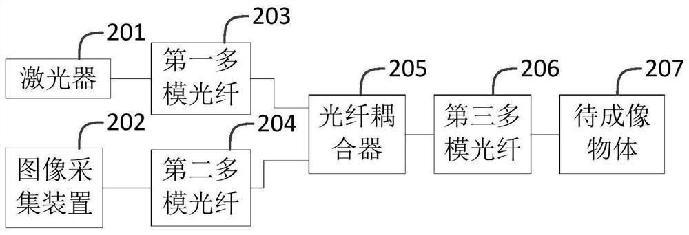
[0040] The optical fiber imaging system in the prior art still contains multiple multimode optical fibers. If the space of the environment where the object to be imaged is narrow, the multiple multimode optical fibers in the optical fiber imaging system may not be able to enter the environment where the object to be imaged is located. , it is impossible to obtain the image of the object to be imaged, resulting in a narrow range of application of the optical fibe...


PUM

PropertyMeasurementUnit
diameteraaaaaaaaaa

Abstract

The embodiment of the invention provides an optical fiber imaging system. The optical fiber imaging system comprises a laser, an image acquisition device, a first multimode optical fiber, a second multimode optical fiber, an optical fiber coupler and a third multimode optical fiber; a first port of the optical fiber coupler is located at one side of the optical fiber coupler, and a second port of the optical fiber coupler is located at the other side of the optical fiber coupler; the first multimode optical fiber is connected with one first port of the optical fiber coupler, and the second multimode optical fiber is connected with the other first port of the optical fiber coupler; the third multimode optical fiber is connected with the second port of the optical fiber coupler; a first light beam generated by the laser reaches the optical fiber coupler through the first multimode optical fiber and irradiates an object to be imaged through the third multimode optical fiber; the first light beam is reflected by the object to be imaged to obtain a second light beam, and the second light beam reaches the optical fiber coupler through the third multimode fiber and reaches the image acquisition device through the second multimode fiber; and the image acquisition device generates an initial image of the object to be imaged. The application range of the optical fiber imaging system is widened.

Description

technical field [0001] The invention relates to the technical field of photoelectric imaging, in particular to an optical fiber imaging system. Background technique [0002] Fiber optic imaging technology has the advantages of low loss and low cost. Therefore, fiber optic imaging technology is widely used in biomedicine, laser technology and other fields. Early fiber optic imaging systems collected images using fiber bundles composed of multiple single-mode fibers, and each single-mode fiber was used to collect an image of a pixel. Containing more single-mode optical fibers leads to a larger diameter of the fiber optic bundle. Therefore, in order to improve the miniaturization of the fiber optic imaging system, the fiber optic bundle in the fiber optic imaging system can be replaced by a single multimode fiber. [0003] see figure 1 , in the prior art, the optical fiber imaging system includes: a laser 101 , an image acquisition device 102 , a first multimode optical fiber...

Claims


Application Information

Patent Timeline
Patent Type & Authority Applications(China)
IPC IPC(8): G02B6/26G02B23/24G02B23/26
CPCG02B6/26G02B23/2407G02B23/26
Inventor 于振明居振宇孟子艺徐坤
Owner BEIJING UNIV OF POSTS & TELECOMM
Why Eureka
Eureka Blog
Learn More