
Connector assembly

A technology of connector components and connectors, which is applied in the direction of connection, electrical components, coupling devices, etc., can solve the problems of increasing the difficulty of circuit board manufacturing and the inability to meet the versatility of connector components, and achieve the effect of saving processing steps and convenient positioning

Pending Publication Date: 2021-09-21
得意精密电子(苏州)有限公司
View PDF0 Cites 0 Cited by
  • Summary
  • Abstract
  • Description
  • Claims
  • Application Information

AI Technical Summary

Problems solved by technology

In this way, it is necessary to set additional fixing holes on the circuit board, which increases the difficulty of manufacturing the circuit board, and this connector assembly can only be matched with one type of circuit board, which cannot meet the universality of the connector assembly. need

Method used


Image

  • Connector assembly
  • Connector assembly
  • Connector assembly

Examples


Embodiment Construction

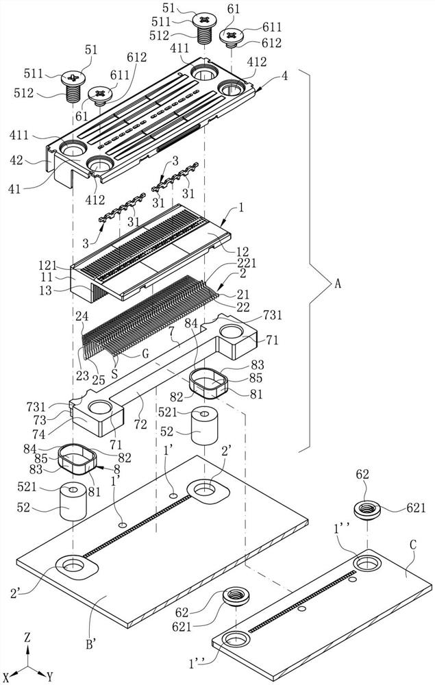
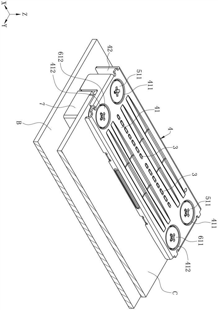
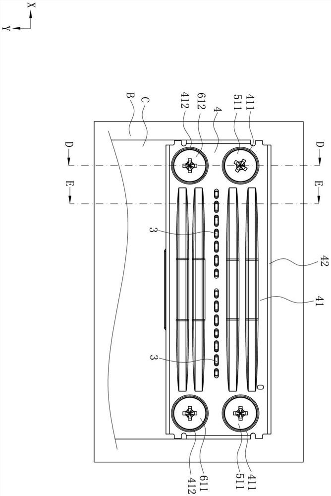
[0028] In order to facilitate a better understanding of the purpose, structure, features and functions of the present invention, the connector assembly A of the present invention will now be further described in conjunction with the drawings and specific embodiments.

[0029] Such as Figure 1 to Figure 8 As shown, the connector assembly A of the present invention defines a front-to-back direction, a left-to-right direction (arrangement direction of a plurality of terminals 2 ) and a vertical direction perpendicular to the front-to-back direction. To facilitate the understanding of the drawings, the forward direction in the front-back direction is the positive direction of the X-axis, the rightward direction in the left-right direction is the positive direction of the Y-axis, and the upward direction in the up-down direction is the positive direction of the Z-axis.

[0030] Such as Figure 1 to Figure 8 As shown, the connector assembly A of the present invention is installed ...


PUM


Abstract

The invention discloses a connector assembly. The connector assembly is installed above a circuit board and used for being in butt joint with a butt joint element. The connector assembly comprises: an electric connector fixed above the circuit board, wherein the electric connector is provided with an insulation body, a plurality of terminals are fixedly arranged on the insulation body, each terminal is provided with a contact part, and the contact parts are abutted against the butt joint element; a supporting main body arranged above the circuit board, positioned below the butt joint element and used for upwards supporting the butt joint element; and at least one connecting piece, wherein the supporting main body is fixedly connected with the electric connector through the connecting piece. Thus, the electric connector can be stably fixed on the circuit board to support the butt joint element, the butt joint element is stably in butt joint with the contact part of the terminal, and the connector assembly can meet the requirement for universality.

Description

【Technical field】 [0001] The invention relates to a connector assembly, in particular to a connector assembly capable of stably fixing mating components. 【Background technique】 [0002] A conventional connector assembly is arranged above a circuit board, which includes an electrical connector used to connect with an electronic card, and a supporting body used to support the electronic card. The supporting body is only placed above the circuit board, or by extending a fixing portion below the supporting body, and the circuit board is provided with a fixing hole corresponding to the fixing portion, so that the supporting body and the The circuit board fixes the supporting body above the circuit board through the interference fit of the fixing part and the fixing hole. The electrical connector has an insulating body, a plurality of terminals are fixed on the insulating body, and each of the terminals has a contact portion for connecting with the electronic card. In this way, ...

Claims


Application Information

Patent Timeline
IPC IPC(8): H01R12/70
CPCH01R12/7011
Inventor 许卫星
Owner 得意精密电子(苏州)有限公司
Learn More