Photovoltaic power station, power equipment and heat dissipation structure thereof

A technology of power equipment and heat dissipation structure, which is applied in the construction of electrical equipment components, transformation equipment structure components, photovoltaic power generation, etc., which can solve the problems of unfavorable PCB layout, large occupied area, unfavorable inverter miniaturization, etc.

Pending Publication Date: 2021-09-21
SUNGROW POWER SUPPLY CO LTD
View PDF6 Cites 0 Cited by
  • Summary
  • Abstract
  • Description
  • Claims
  • Application Information

AI Technical Summary

Problems solved by technology

[0002] At present, the string inverter includes a boost circuit and an inverter circuit, wherein the boost circuit includes at least four boost modules, the inverter circuit includes a three-phase inverter module, and both the boost module and the inverter module are heating modules. Therefore, a heat dissipation mechanism must be set up to dissipate heat for the two modules, such as Figure 1-Figure 3 As shown, since the booster circuit and the inverter circuit cannot be combined due to safety regulations, and the auxiliary circuits and absorbing circuits of the two also need space to be placed, the current heat dissipation structure layout combines the three-phase inverter module and the multi-phase inverter module. The two boost modules are all set on the same surface of a heat dissipation substrate and are arranged in rows at intervals. The inverter module row and the boost module row are arranged in a staggered manner according to the distance from the fan unit, and the radiator is on the other side of the heat dissipation substrate. On the surface, it corresponds to the position of the inverter module and the booster module. This layout structure causes the airflow output by the fan unit to first flow through the radiator of the booster module closer to the fan unit, and then flow through the heat dissipation of the rear inverter module. At this time, the temperature of the airflow increases and the flow rate decreases, which is not conducive to the heat dissipation of the inverter module. At the same time, the two modules are installed on the same surface of the same heat dissipation substrate, occupying a large area, which is not conducive to PCB layout, and will also cause The increase in the width of the inverter is not conducive to the miniaturization of the inverter

Method used


Image

  • Photovoltaic power station, power equipment and heat dissipation structure thereof
  • Photovoltaic power station, power equipment and heat dissipation structure thereof
  • Photovoltaic power station, power equipment and heat dissipation structure thereof

Examples


Embodiment Construction

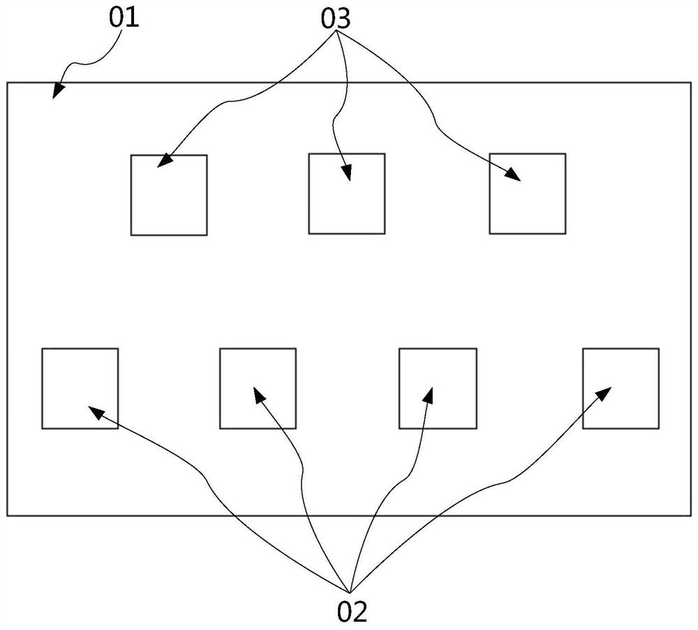
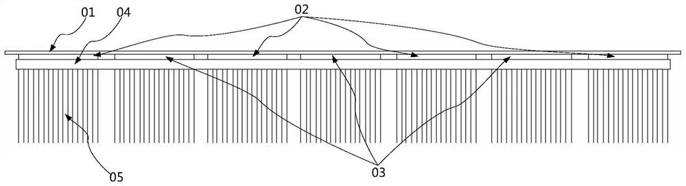
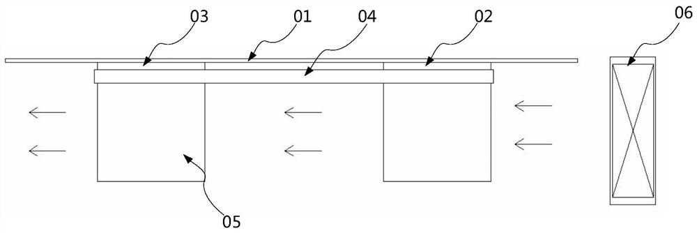
[0032] The embodiment of the present invention discloses a heat dissipation structure of electric equipment. The heat dissipation structure of electric equipment is designed so that the heat dissipation effects of different circuit modules tend to be consistent, the heat dissipation effect is improved, and the space utilization rate is improved, so as to facilitate the miniaturization of electric equipment. design.

[0033] The embodiment of the present invention also discloses an electric power equipment and a photovoltaic power station. The heat dissipation structure of the electric power equipment is applied to ensure good heat dissipation of each heating element.

[0034] The following will clearly and completely describe the technical solutions in the embodiments of the present invention with reference to the accompanying drawings in the embodiments of the present invention. Obviously, the described embodiments are only some, not all, embodiments of the present invention. ...


PUM


Abstract

The invention discloses a photovoltaic power station, power equipment and a heat dissipation structure thereof. The heat dissipation structure comprises two groups of heat dissipation components, each heat dissipation component comprises a heat dissipation substrate and a radiator row arranged on the first surface of the heat dissipation substrate, the radiator row comprises a plurality of radiators arranged at intervals, the first surfaces of the two heat dissipation substrates are oppositely arranged, and at least part of the radiators of one radiator row are embedded into the gap of the other radiator row. According to the structure, the distances between the radiators on the two heat dissipation substrates and the fan set are basically consistent, and the radiators on the two heat dissipation substrates can exchange heat with airflow provided by the fan set at the same time, so that the heat dissipation effects of the two tend to be consistent; and meanwhile, the two heat dissipation substrates are oppositely arranged, and the two groups of heat dissipation devices are mutually staggered and embedded, so that the space utilization rate of the heat dissipation structure can be improved, the space occupation of the heat dissipation structure in the width direction is reduced on the premise that the thickness of the heat dissipation structure is not changed basically, and convenience is provided for miniaturization design of power equipment.

Description

technical field [0001] The present invention relates to the technical field of power equipment heat dissipation, and more specifically, relates to a power equipment heat dissipation structure, and also relates to a power equipment and a photovoltaic power station. Background technique [0002] At present, the string inverter includes a boost circuit and an inverter circuit, wherein the boost circuit includes at least four boost modules, the inverter circuit includes a three-phase inverter module, and both the boost module and the inverter module are heating modules. Therefore, a heat dissipation mechanism must be set up to dissipate heat for the two modules, such as Figure 1-Figure 3 As shown, since the booster circuit and the inverter circuit cannot be combined due to safety regulations, and the auxiliary circuits and absorbing circuits of the two also need space to be placed, the current heat dissipation structure layout combines the three-phase inverter module and the mul...

Claims


Application Information

Patent Timeline
Patent Type & Authority Applications(China)
IPC IPC(8): H02S40/32H02M7/00H05K7/20
CPCH02S40/32H02M7/003H05K7/205H05K7/20145Y02E10/56
Inventor 吴杰
Owner SUNGROW POWER SUPPLY CO LTD
Why Eureka
Try Eureka