Printing machine pressure adjusting device and control method thereof

A technology of pressure regulation and control method, which is applied in the direction of printing presses, rotary printing presses, general parts of printing machinery, etc. It can solve the problems of inability to realize digital formula management, inability to realize digital position storage and memory, and achieve convenient and fast pressure adjustment, Easy to adjust the effect

Active Publication Date: 2021-09-24
潍坊东航印刷科技股份有限公司
View PDF4 Cites 0 Cited by
  • Summary
  • Abstract
  • Description
  • Claims
  • Application Information

AI Technical Summary

Problems solved by technology

The fine adjustment of the pressure during the printing process is realized by manually adjusting the mechanical limit, but the digital position storage and memory cannot be realized, and thus the digital formula management cannot be realized

Method used


Image

  • Printing machine pressure adjusting device and control method thereof
  • Printing machine pressure adjusting device and control method thereof
  • Printing machine pressure adjusting device and control method thereof

Examples


Embodiment 1

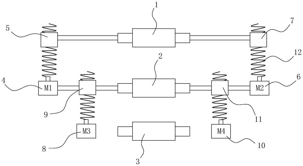
[0035] Such as figure 1 As shown, a pressure regulating device for printing presses includes an anigraph roll, a plate roll and a printing roll arranged in parallel, the plate roll is located between the screen roll and the printing roll, between the screen roll and the plate roll and between the plate roll and the plate roll An adjustment mechanism for adjusting the distance between the rollers is provided respectively, and the adjustment mechanism is electrically connected with a control system for inputting control commands.

[0036] Such as figure 1 As shown, there are four adjustment mechanisms, and the adjustment mechanisms are composed of a servo motor, a lead screw connected to the output shaft of the servo motor, and a thread sleeve fitted on the lead screw. Wherein, a first servo motor and a second servo motor are respectively installed at both ends of the plate roller, and a first wire sleeve and a second wire sleeve matched with the first servo motor and the secon...

Embodiment 2

[0038] The control method of the printing press pressure regulating device in the first embodiment includes the following steps:

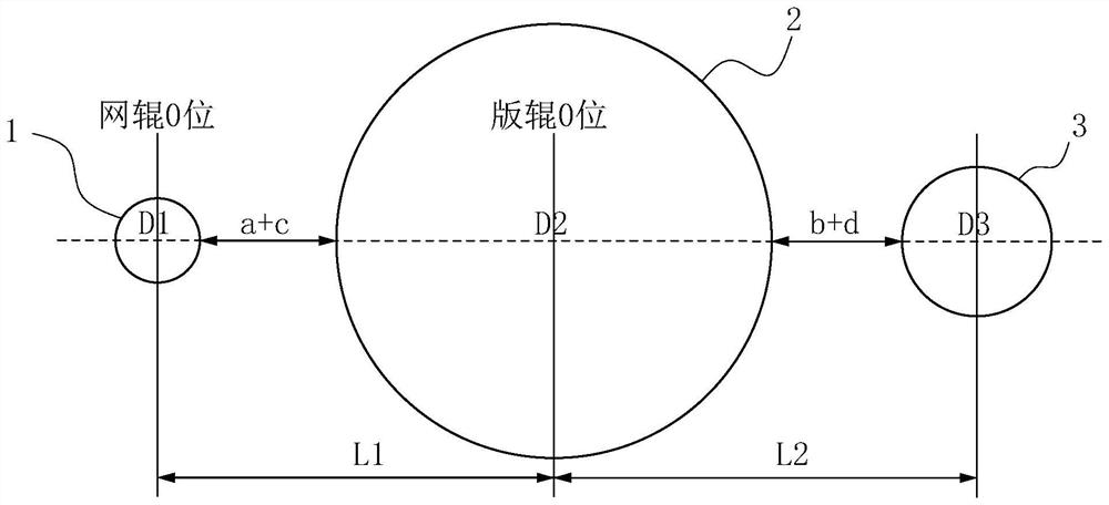
[0039] Step A1, whether the control system inputs a slide-out command, if input, the adjustment mechanism returns to zero; if not input, perform step A2; wherein, the zero position of the adjustment mechanism is determined by the control system according to the length of the lead screw, the screen roller, the printing roller, the maximum Calculated from the roll diameter or the diameter of the smallest roll.

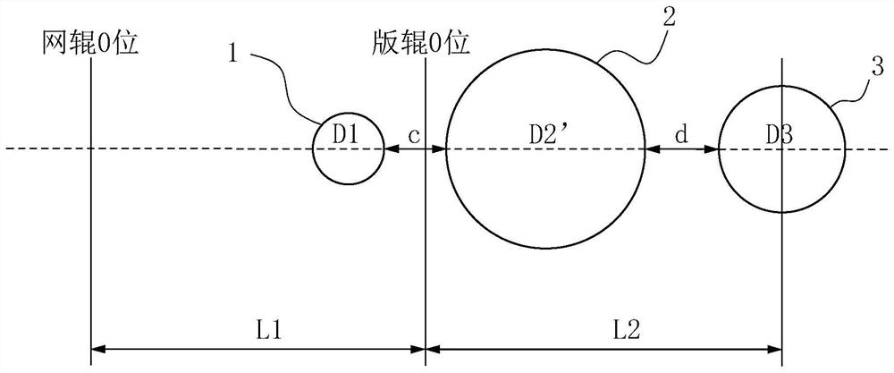
[0040] Step A2, whether the control system inputs a slide-in command, if so, the first servo motor and the second servo motor drive the moving distance S1 of the net roll to enter the net roll off-press position, and the third servo motor and the fourth servo motor drive the moving distance of the plate roll S2 enters the release position of the plate roller, and then executes steps A3 and A6; if not input, the adjustment mechanism remains at...


PUM


Abstract

The invention discloses a printing machine pressure adjusting device and a control method thereof, and belongs to the technical field of printing machines. The printing machine pressure adjusting device comprises a screen roller, a plate roller and a printing roller, all of which are arranged in parallel. The plate roller is located between the screen roller and the printing roller, adjusting mechanisms used for adjusting the distance between the rollers are arranged between the screen roller and the plate roller and between the plate roller and the printing roller correspondingly, and the adjusting mechanisms are electrically connected with a control system used for inputting control instructions. The number of the adjusting mechanisms is four, and each adjusting mechanism is composed of a servo motor, a lead screw connected to an output shaft of the servo motor and a screw sleeve arranged on the lead screw in a sleeving manner. According to the control method of the device, the control system automatically calculates the clutch pressure position and the sliding-in and sliding-out position and is controlled to reach the clutch pressure position and the sliding-in and sliding-out position, meanwhile, a manual fine adjustment system is arranged, manual adjustment can be achieved according to the printing effect of a product, accurate positioning can be achieved, storability is achieved, and pressure adjustment is more convenient and faster.

Description

technical field [0001] The invention belongs to the technical field of printing machines, and in particular relates to a printing machine pressure regulating device and a control method thereof. Background technique [0002] The screen roll, plate roll and printing roll of the traditional printing machine are distributed in a square shape. The screen roll is adjusted in the horizontal direction by a pressure adjustment mechanism, and the plate roll is adjusted in the vertical direction by another pressure adjustment mechanism. The conventional pressure regulating mechanism is composed of a solenoid valve, a valve island, and a cylinder. The switching gas of the valve island is controlled through the energization and de-energization of the solenoid valve, and then the expansion and contraction of the cylinder is controlled to achieve the purpose of controlling the clutch pressure. The fine adjustment of the pressure during the printing process is realized by manually adjustin...

Claims


Application Information

Patent Timeline
Patent Type & Authority Applications(China)
IPC IPC(8): B41F13/34B41F33/00
CPCB41F13/34B41F33/00
Inventor 李训艳王云孟祥杰边国栋
Owner 潍坊东航印刷科技股份有限公司
Why Eureka
Try Eureka