Satellite surface multi-layer heat insulation assembly with strong electromagnetic environment protection capability
A multi-layer thermal insulation component and strong electromagnetic technology, which is applied in the direction of thermal protection devices of aerospace vehicles, artificial satellites, space navigation equipment, etc. Good thermal control temperature characteristics, avoid strong electromagnetic wave interference, prevent burning effect
- Summary
- Abstract
- Description
- Claims
- Application Information
AI Technical Summary
Problems solved by technology
Method used
Image

Examples
Embodiment 1
[0036] Please refer to figure 1 The shown structure schematic diagram of the first embodiment of a star surface multilayer heat insulation assembly provided by the application with strong electromagnetic environment protection capability, including:
[0037] layered components,
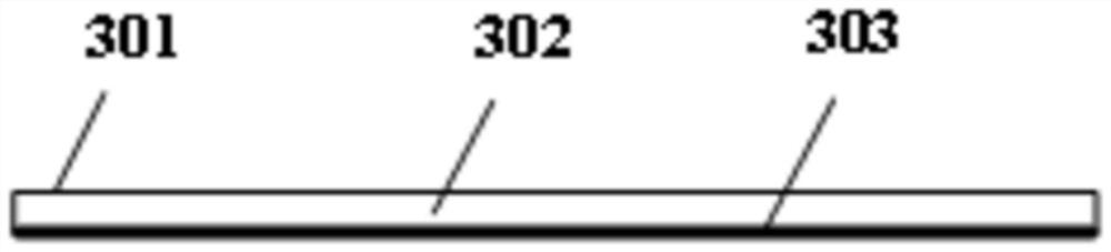
[0038] The anti-electromagnetic reinforcement mask group 3 is coated on the surface of the laminated assembly; the anti-electromagnetic reinforcement mask group 3 is connected to the laminated assembly by sutures 4;
[0039] The anti-electromagnetic reinforcement mask set 3 is provided with a polyimide layer 302 and a metal layer 303, and the metal layer 303 is arranged relatively close to the laminated assembly;
[0040] In use, the laminated assembly faces the product to be protected, and the polyimide layer 302 faces the external environment.
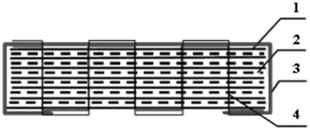
[0041] In this example, if figure 2 As shown, the laminated assembly has a reflective layer 1, the number of reflective layers 1 is at least five and st...
Embodiment 2
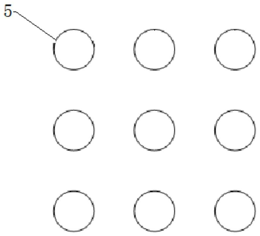
[0057] Such as Figure 4 As shown, when some cabin penetration cables need to penetrate the cabin, there are holes and gaps on the star, and high-power microwaves are easily coupled into the interior of the star through these holes, causing interference and even burning of sensitive devices inside the star. To block.
[0058] In order to prevent the problem of wave leakage in holes and gaps caused by cables, waveguides, pipelines, etc., the anti-electromagnetic reinforcement mask set 3 is designed as a structure that wraps the mask set 6 in holes and gaps;
[0059] Specifically, the hole gap wrapping mask group 6 is used to absorb the leakage wave caused by the cable lead, so that the power of the high-power microwave is greatly reduced when it reaches the hole through the cabin;
[0060] Hole and gap wrapping mask group 6 has the outer layer carburized polyimide layer 601, the middle metal layer 602 and the inner layer carburized polyimide layer 603 arranged in sequence, and...
PUM
| Property | Measurement | Unit |
|---|---|---|
| Diameter | aaaaa | aaaaa |
| Thickness | aaaaa | aaaaa |
| Thickness | aaaaa | aaaaa |
Abstract
Description
Claims
Application Information