
Concrete conveying belt device and its control method

A belt device and belt technology, applied in conveyor control devices, conveyors, conveyor objects, etc., can solve the problems of slow walking, high cost of lifting equipment, and large limitations, so as to prevent cold seams in construction and ensure pouring. Quality, the effect that meets the needs of pouring

Active Publication Date: 2022-02-15
THE GUANGDONG NO 3 WATER CONSERVANCY & HYDRO ELECTRIC ENG BOARD CO LTD
View PDF0 Cites 0 Cited by
  • Summary
  • Abstract
  • Description
  • Claims
  • Application Information

AI Technical Summary

Problems solved by technology

[0005] 1. The hoisting equipment cooperates with the method of hoisting and pouring into the warehouse. Because the weight to be lifted is relatively large, the cost of the hoisting equipment to be invested is relatively high, and the speed of this method is slow, the speed is about 15-30m3 / hour. For some warehouses with relatively large positions position, the warehousing strength does not meet the requirements
[0006] 2. Crawler type distribution machine, due to its huge body, slow walking and overall weight of 90t, it is difficult to dispatch and move between positions. At the same time, this type of distribution machine has high requirements for construction roads and sites
For projects with limited construction sites and difficult construction roads, there are limitations in use
[0007] 3. For fixed distribution machines, due to the limited coverage, for large-scale projects, multiple distribution machines need to be connected in series and used in combination. However, for linear projects like ship locks, multiple units are required to relay concrete. Due to the long line, the quality of the concrete is difficult to guarantee and the cost is high
[0008] 4. The direct entry of the excavator into the warehouse is limited by the arm span of the excavator, and the coverage area is small
[0009] 5. Cable cars need to be used in large-scale projects such as large-scale gravity dams or arch dams, which have relatively large limitations.

Method used


Image

  • Concrete conveying belt device and its control method
  • Concrete conveying belt device and its control method
  • Concrete conveying belt device and its control method

Examples


Embodiment Construction

[0039] The specific implementation manner of the present invention will be described in detail below in conjunction with the accompanying drawings.

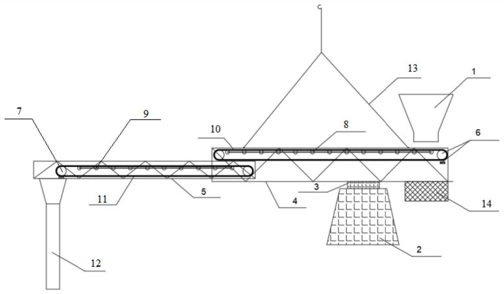
[0040] ginseng figure 1As shown, the present invention provides a concrete conveying belt device, including a feeding mechanism 1, a conveying system and a feeding pipe 15, and the conveying system includes a main truss belt set, a main truss 4, a secondary truss 5, and a secondary truss belt set And the driving device 3, the driving device 3 here can be a rotating motor, the input end of the main truss belt set is located below the feeding mechanism, and the output end of the secondary truss belt set is connected with the described feeding pipe. The main truss belt set is located above the secondary truss belt set, and the output end of the main truss belt set is connected to the input end of the secondary truss belt set; the main truss belt set is installed on the main truss, and the A secondary truss belt set is installed on ...


PUM


Abstract

A concrete conveying belt device and its control method provided by the present invention include a feeding mechanism, a conveying system and a feeding pipe, the conveying system includes a main truss belt set, a main truss, a secondary truss, and a secondary truss belt set. The main truss belt set is located above the secondary truss belt set, and the output end of the main truss belt set is connected to the input end of the secondary truss belt set; the main truss belt set is installed on the main truss, and the secondary A secondary truss belt set is installed on the truss; the main truss belt set includes a main truss belt pulley, a main truss belt support roller and a main truss belt, the belt is provided with a main truss belt support roller, and the belt is connected to the main truss belt The above-mentioned main truss is connected with the belt roller; it can be quickly assembled on site, and can realize flexible scheduling between concrete pouring warehouse surfaces.

Description

technical field [0001] The invention relates to the field of large-volume concrete storage methods, in particular to a simple belt conveying device for concrete. Background technique [0002] The Baishiyao hub ship lock project includes building a new second-line ship lock and rebuilding a first-line ship lock. The main body of the ship lock is a reinforced concrete structure, and most of the pouring units are large-volume concrete, which requires a large amount of concrete pouring and high temperature control requirements. [0003] In order to reduce the amount of cement and reduce the heat of hydration, mass concrete generally adopts a multi-graded concrete mix with large particle size and small slump. The storage means of this type of concrete are relatively limited, and conventional pumping cannot be realized. [0004] Disadvantages of existing technology: [0005] 1. The hoisting equipment cooperates with the method of hoisting and pouring into the warehouse. Because...

Claims


Application Information

Patent Timeline
Patent Type & Authority Patents(China)
IPC IPC(8): B65G15/32B65G15/12B65G15/60B65G21/20B65G23/04B65G43/08B65G43/10B65G47/18B65G65/46E02D15/02E02B7/02
CPCE02D15/02E02B7/02B65G15/32B65G15/12B65G15/60B65G23/04B65G43/08B65G43/10B65G21/2081B65G47/18B65G65/46
Inventor 李小鹏李岩刘茜茜吕凯杜耀初胡芬聂清念揭文博
Owner THE GUANGDONG NO 3 WATER CONSERVANCY & HYDRO ELECTRIC ENG BOARD CO LTD
Learn More