Heat treatment equipment for production of high-ductility ribbed steel bars

A heat treatment equipment and technology of ribbed steel bars, which are applied in the field of metal processing, can solve the problems of short cooling water flow, inability to have multiple heat treatments of steel bars at the same time, and rapid drying of cooling water, so as to achieve perfect cooling effect.

Pending Publication Date: 2021-09-24
河南省鼎鼎实业有限公司
View PDF6 Cites 1 Cited by
  • Summary
  • Abstract
  • Description
  • Claims
  • Application Information

AI Technical Summary

Problems solved by technology

[0007] The object of the present invention is to provide a kind of heat treatment equipment for the production of high ductility ribbed steel bar, by setting the main extrusion roller, power supply module, top cover and air outlet box, it solves the problem

Method used


Image

  • Heat treatment equipment for production of high-ductility ribbed steel bars
  • Heat treatment equipment for production of high-ductility ribbed steel bars
  • Heat treatment equipment for production of high-ductility ribbed steel bars

Examples


Embodiment 1

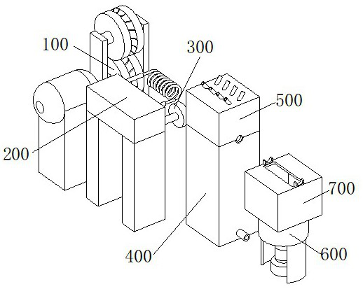
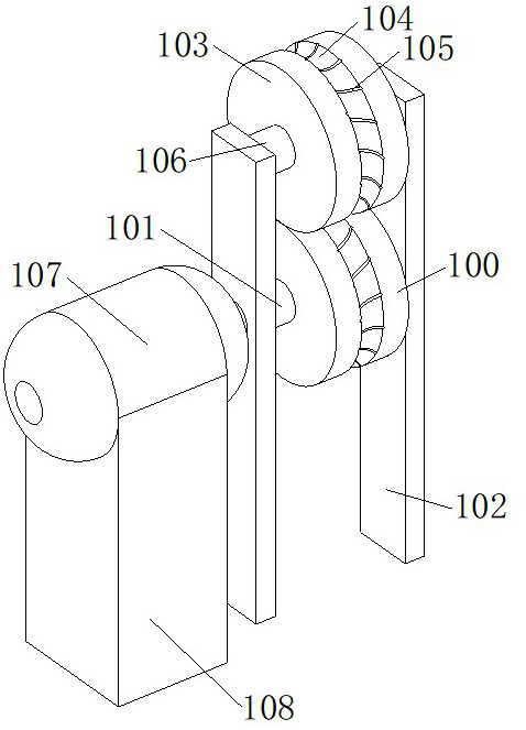
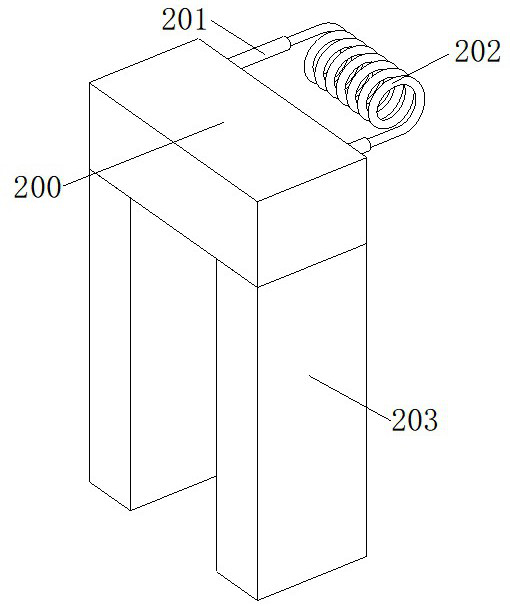
[0036] see Figure 1-8 As shown, the present invention is a heat treatment equipment for the production of high-ductility ribbed steel bars, including a main extrusion roll 100, a power supply module 200, a top cover 500 and an air outlet box 700, and an auxiliary extrusion roll is arranged on the top of the main extrusion roll 100 103, the main extrusion roller 100 cooperates with the auxiliary extrusion roller 103 when driven by the servo motor 107, and squeezes the ribs of the steel bar to be processed. The middle of the main extrusion roller 100 and the auxiliary extrusion roller 103 are all A steel bar extruding groove 104 is provided. When the steel bar is being squeezed, it moves in the steel bar extruding groove 104, so that the steel bar is transported to the induction heater 202 on the power module 200. The main extrusion of the inner wall of the steel bar extruding groove 104 Both the pressure roller 100 and the auxiliary extrusion roller 103 are provided with rib e...

Embodiment 2

[0045] Based on the heat treatment equipment for the production of high-ductility ribbed steel bars described in Embodiment 1, when the required heat treatment is performed on the steel bars, the rotation speed of the servo motor 107 that drives the main extrusion roller 100 is adjusted so that the speed at which the steel bars pass through the induction heater 202 changes. , so that the temperature of the heat treatment of the steel bar and the cooling time of the water tank 400 and the top cover 500 are changed, so that the temperature of the heat treatment of the steel bars with different components is different, and the driving speed of the same steel bar can be changed by the servo motor 107. The temperature after the induction heater 202 is heated is different, the time length for cooling after heating is different, and different heat treatments are performed. In addition, the liquid that is transported into the top cover 500 in the water inlet pipe 502 on the top cover 50...


PUM


Abstract

The invention discloses heat treatment equipment for production of high-ductility ribbed steel bars, and relates to the technical field of metal processing. The equipment comprises a main extrusion roller, a power module, a top cover and an air outlet box, an auxiliary extrusion roller is arranged at the top of the main extrusion roller, an induction heater is fixed to the front side of the power module, a water inlet pipe is fixed to the top of the top cover, and an air outlet is transversely formed in the center of the top of the air outlet box. Through the arrangement of the main extrusion roller, the power module, the top cover and the air outlet box, the problems that existing heat treatment equipment for high-ductility ribbed steel bar production cannot have multiple heat treatment functions on steel bars at the same time, the passing time of cooling water flow on the steel bars is too short, and cooling water on the steel bars cannot be quickly blow-dried are solved; and multiple heat treatments of the reinforcing steel bars can be carried out on the same equipment, the cooling effect of the reinforcing steel bars after heat treatment is good, and the reinforcing steel bars can be rapidly dried to prevent corrosion of the reinforcing steel bars.

Description

technical field [0001] The invention belongs to the technical field of metal processing, in particular to heat treatment equipment for producing high-ductility ribbed steel bars. Background technique [0002] Steel bar refers to the steel used for reinforced concrete and prestressed reinforced concrete. Its cross section is circular, sometimes square with rounded corners, including smooth round steel bar, ribbed steel bar, and twisted steel bar. , by means of heating, heat preservation and cooling, changing the chemical composition and structure of the surface or inside of the material to obtain the desired performance of a metal thermal processing process, the ribbed steel bar is usually formed by cold rolling, which will produce a certain amount of internal stress , resulting in certain deviations in the mechanical properties of steel bars during use, which will affect the results of final use. Therefore, it is necessary to eliminate internal stress through heat treatment,...

Claims


Application Information

Patent Timeline
IPC IPC(8): C21D8/08F26B21/00
CPCC21D8/08F26B21/00
Inventor 王焕景庄振伟贾世方蒋凯明
Owner 河南省鼎鼎实业有限公司
Why Eureka
Try Eureka