Roller chain suspension strength machining clamp, vacuum coating equipment and shot blasting equipment
A roller chain and fixture technology, used in metal processing equipment, vacuum evaporation coating, manufacturing tools, etc., can solve the problems of lack of processing fixture processing, inability to use high-strength conveying operations, low mechanical strength and rigidity, etc. Avoid rollover or rollover tendency, improve surface strength, improve fatigue strength effect
- Summary
- Abstract
- Description
- Claims
- Application Information
AI Technical Summary
Problems solved by technology
Method used
Image
Examples
Embodiment 1
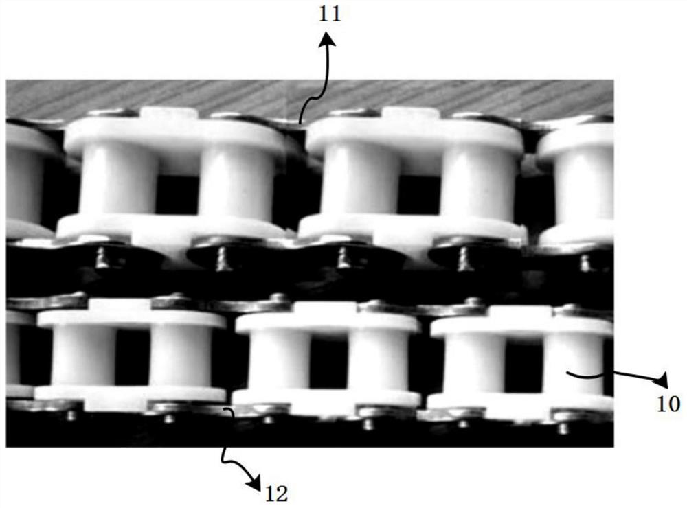
[0061] Such as figure 1 , Figure 10 As shown, the roller chain applied to the roller chain suspension strength processing jig 1 provided in this embodiment is a plurality of upper outer chain plates 11, lower outer chain plates 12, and pins made of magnetically conductive metal (such as iron). And a plurality of inner chain plates and sleeves (hereinafter referred to as inner chain components 10 ) made of engineering plastics.
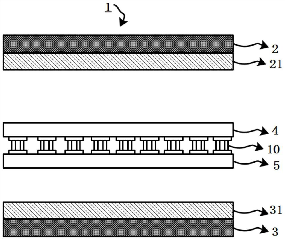
[0062] Such as figure 2 As shown, the processing fixture 1 provided in this embodiment is composed of a top plate 2 , a base 3 , a first electromagnet 21 , a first on / off control switch 22 , a first mold 4 , a second mold 5 and a control unit 6 .
[0063] Wherein, the top plate 2 and the base 3 can at least move up and down in the vertical direction under the external driving force, and the top plate 2 and the base 3 are arranged at intervals up and down.
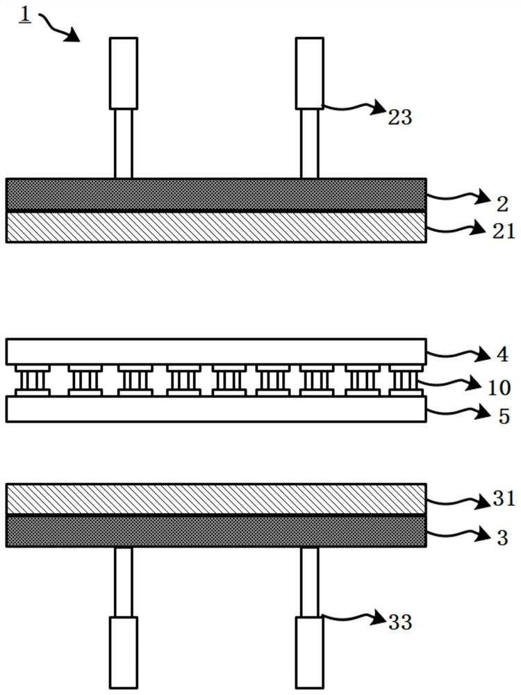
[0064] Such as image 3 As shown, in one embodiment, the external driving force comes from: ...
Embodiment 2
[0073] This embodiment is an extension of Embodiment 1, such as Figure 4 , Figure 10 As shown, the processing fixture 1 also includes third electromagnets 211, 212 respectively arranged at both ends of the first electromagnet 21 and connected to the control unit 6 and used to control the third electromagnets 211, 212 on / off and the magnitude of the current. The first current control switch 213 of the second electromagnet 31 and the fourth electromagnet 311, 312 respectively arranged at both ends of the second electromagnet 31 are connected with the control unit 6 and are used to control the power on / off and current of the fourth electromagnet 311, 312 respectively. The size of the second current control switch 313; the third electromagnet 211, 212 produces the same magnetism as the first mold 4 when energized, and the fourth electromagnet 311, 312 produces the opposite magnetism to the second mold 5 when energized.
[0074] Specifically, the control unit 6 can be operated t...
Embodiment 3
[0077] This embodiment is an extension of Embodiment 1, such as Figure 5 , Figure 10 As shown, the processing fixture 1 also includes a third current control switch 217, 317 connected to the control unit 6, slide rails 214, 314 respectively arranged on the first electromagnet 21 and the second electromagnet 31, and arranged on the slide rail 214. The mobile carts 215, 315 connected to the control unit 6 on , 314, wherein, the bottom of the mobile carts 215, 315 is provided with a fifth electromagnet 216, 316.
[0078] The mobile trolleys 215, 315 can self-move along the slide rails 214, 314 based on the movement signal output by the control unit 6, and then drive the fifth electromagnet 216, 316 to self-move along the slide rails 214, 314, which is equivalent to moving along the first and second electromagnets. The irons 21, 31 are translated; wherein, the fifth electromagnet 216 produces the same magnetic force as the first mold 4 when energized, and the fifth electromagne...
PUM
 Abstract
Description
Claims
Application Information
 - R&D
- Intellectual Property
- Life Sciences
- Materials
- Tech Scout
- Unparalleled Data Quality
- Higher Quality Content
- 60% Fewer Hallucinations
Browse by: Latest US Patents, China's latest patents, Technical Efficacy Thesaurus, Application Domain, Technology Topic, Popular Technical Reports.
© 2025 PatSnap. All rights reserved.Legal|Privacy policy|Modern Slavery Act Transparency Statement|Sitemap|About US| Contact US: help@patsnap.com


