Relay with safety device

A safety device and relay technology, applied in relays, electromagnetic relays, electromagnetic relay detailed information and other directions, can solve the problems of cracking, thinning, and easy damage to the electromagnet core and armature, so as to prolong the service life, save costs, and avoid replacement. Effect

Active Publication Date: 2021-09-24
中汇瑞德电子(芜湖)有限公司
View PDF11 Cites 0 Cited by
  • Summary
  • Abstract
  • Description
  • Claims
  • Application Information

AI Technical Summary

Problems solved by technology

[0004]The disadvantage of the existing technology is that an arc will be generated between the electromagnet core and the armature at the moment of electrification, and the high temperature generated by the arc will cause the gasket Melting makes the gasket no longer have the anti-collisio

Method used


Image

  • Relay with safety device
  • Relay with safety device
  • Relay with safety device

Examples


Embodiment 1

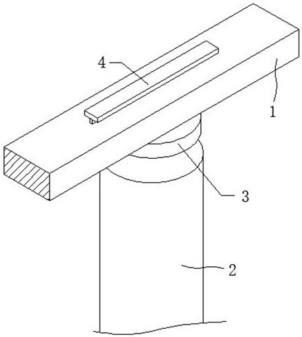
[0031] like Figure 1 to 3 As shown, a relay having a safety device provided by the present invention, including the armature 1 and the electromagnetic iron core 2, in an instantaneous moment, the electric arc is generated, and the melting point of the high temperature spacer 3 is high, so that the high temperature gasket 3 There is no deformation due to the high temperature generated by the arc, avoiding the direct hitting of the electric or high-temperature gasket 3, so that the high-temperature gasket 3 is damaged, extend the service life of high temperature gasket 3, to avoid the armature 1 and electromagnetic iron core 2 collision.

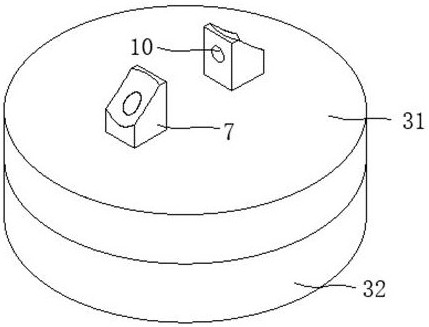
[0032] Among them, if figure 2 with image 3 As shown, the ceramic sheet 31, the carbon fiber cloth 32 and the polytetrafluoroethylene sheet 33 are high temperature resistant materials, and the high temperature produced by the arc does not affect the ceramic sheet 31, the carbon fiber cloth 32, and the polytetrafluoroethylene sheet 33, while The ce...

Embodiment 2

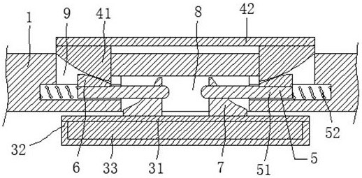
[0034] like Figures 2 to 6 As shown, the locking member 5 is provided in the armature 1 to fix the high temperature spacer 3, sliding through the sliding slot 11 through the sliding rod 51, lock the slider 51 to lock or relieve the lock lock block 7, when the card block 7 When the groove 8 is inserted, the slider 51 is inserted into the through hole 10, so that the high temperature spacer 3 can be mounted on the armature 1, and when the high temperature spacer 3 is damaged, the slider 51 moves to the spring 52, And replace the new high temperature sensing spacer 3, under the spring 52 elastic action, the slider 51 is inserted into the through hole 10 of the new high temperature gasket 3.

Embodiment 3

[0036] Further, such as figure 2 , Figure 4 , Figure 5 with Image 6 As shown, the driving member 4 is provided in the armature 1 to quickly remove the high temperature spacer 3, by applying a pressure on the active sheet 42, so that the shift block 41 slides in the card slot 9, and transmitted to the power block 6. On, the two sides of the shroud block 41 and the force block 6 are in the convex curve surface such that the two resilient blocks 6 are driven by the two slide rods 51, respectively, to keep the slider 51 from pass The holes 10 are detached, and the locking resistant high temperature gasket 3 is released.


PUM


Abstract

The invention relates to the technical field of relays with safety devices, and discloses a relay with a safety device, which comprises an armature and an electromagnetic iron core, a high-temperature-resistant gasket is arranged on the side surface, adjacent to the electromagnetic iron core, of the armature, the high-temperature-resistant gasket is assembled in a way that when a circuit is switched on, the high-temperature-resistant gasket cannot be melted, the ceramic plate, the carbon fiber cloth and the polytetrafluoroethylene plate are all made of high-temperature-resistant materials, deformation caused by high temperature generated by electric arcs is avoided, the electric arcs are prevented from directly puncturing the high-temperature-resistant gasket, the service life of the high-temperature-resistant gasket is prolonged, meanwhile, the ceramic plate, the carbon fiber cloth and the polytetrafluoroethylene plate are all made of non-conducting materials, parallel connection of two circuits can be avoided, meanwhile, the high-temperature-resistant gasket is convenient to replace, if the high-temperature-resistant gasket is damaged, the high-temperature-resistant gasket is unlocked by the locking piece through the driving piece, and a new high-temperature-resistant gasket is replaced, so that replacement of the whole relay is avoided, and the cost is saved.

Description

Technical field [0001] The present invention relates to a relay technique having a safety device, and is specifically a relay having a safety device. Background technique [0002] Relay, also known as the electricity, is an electronic control device, which has a control system and a control system, typically applied to the automatic control circuitry, and can control the large current with a smaller current. Therefore, in the circuit, automatic adjustment, security protection, conversion circuit, etc. are used. [0003] According to Patent No. 20,2010,908119.4, a pair of fixed terminals are disclosed, and the pair of fixed terminals comprise a first plate portion and a fixed contact disposed at the first plate; a movable contact piece, A pair of movable contacts configured relative to the fixed contact, and set to the contact direction of the movable contact with the fixed contact contact and the movable contact from the fixed touch. The point is in contact with the separation di...

Claims


Application Information

Patent Timeline
IPC IPC(8): H01H50/16H01H50/18
CPCH01H50/16H01H50/18
Inventor 杜展
Owner 中汇瑞德电子(芜湖)有限公司
Why Eureka
Try Eureka