Robot for wiring welding and welding method thereof
A robot and wire technology, applied in the direction of welding/welding connection, line/collector parts, connection, etc., can solve problems affecting the work of the computer room, cumbersome calibration process, welding errors, etc., to improve intelligence, realize automation, Avoid the spread effect
- Summary
- Abstract
- Description
- Claims
- Application Information
AI Technical Summary
Problems solved by technology
Method used
Image
Examples
Embodiment 1
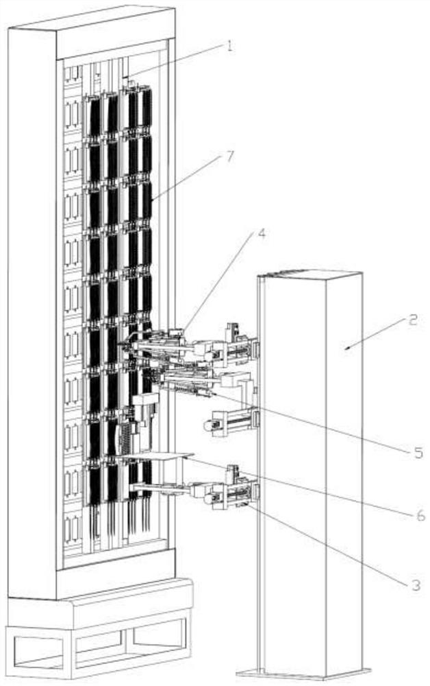
[0083] Such as figure 1 As shown, a robot for wire welding includes a lead frame 1 , an electric control stand 2 , a slide table 3 , an image acquisition device, a first manipulator 4 and a second manipulator 5 . Wherein the first manipulator 4 and the second manipulator 5 are respectively connected with the sliding table 3 through the sliding structure, and the sliding table 3 is connected with the electric control stand 2 through the sliding structure, and the sliding structure is a ball screw structure; the image acquisition device is arranged on the first On the manipulator 4 or the second manipulator 5, in this example, the image acquisition device is set on the first manipulator 4; in this example, the lead frame 1 is fixedly set on the signal cabinet to be welded.
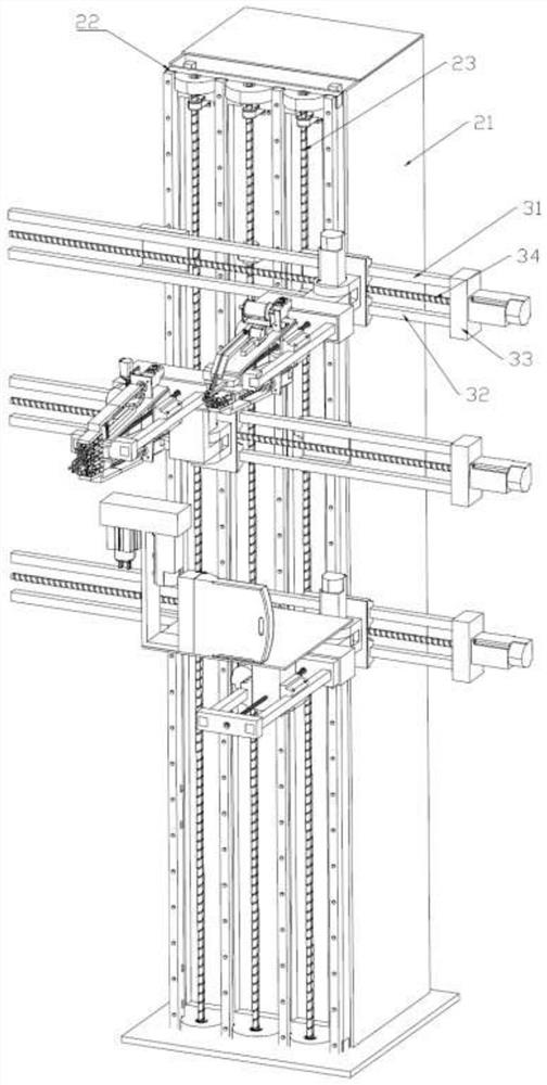
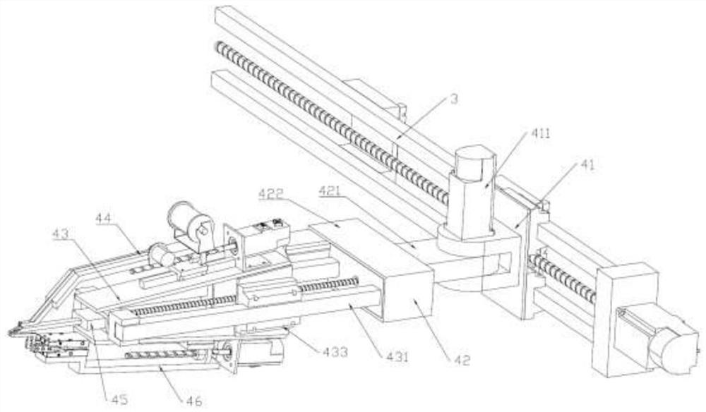
[0084] Such as figure 2As shown, the electric control stand 2 includes a box body 21, a movement board 22 and a control module; wherein the control module is arranged inside the box body 21; the movement b...
Embodiment 2
[0136] Such as Figure 13-16 As shown, this embodiment is obtained based on the improvement of the first embodiment, wherein the lead frame 1 is provided with a communication verification device-7. The communication checking device one 7 comprises base plate one 71, lifting rod 72, blade head one 73, blade bar 74 and blade frame 75; wherein lifting rod 72 is arranged on base plate one 71, and lifting rod 72 can be arranged on base plate one 71 Move in the waist-shaped hole space; the blade frame 75 is arranged on the bottom plate 71; the blade bar 74 is arranged on the blade frame 75, and each blade frame 75 is provided with two blade bars 74, and one of the blade bars 74 is fixedly arranged on the blade on the frame 75; another blade rod 74 is slidably arranged in the blade frame 75, and one end of the blade rod 74 is connected with the pull rod 72, and the blade rod 74 is driven by the action of the pull rod 72; the blade head 73 is evenly arranged on the blade on the rod 7...
Embodiment 3
[0141] Such as Figure 17 , 18As shown, this embodiment is obtained based on the improvement of the first embodiment, wherein the lead frame 1 is provided with a communication verification device 2 8 . The communication verification device 2 8 includes a base plate 2 81, a slide plate 83, a blade head 2 86 and a limiter 87, wherein the slide plate 83 is slidably arranged on the slide rail of the base plate 2 81; the limiter 87 is arranged on the base plate 2 81 and the slide plate 83 The gap is used to limit the sliding range between the second bottom plate 81 and the sliding plate 83; the second blade head 86 is evenly arranged on the second bottom plate 81 and the sliding plate 83. Described limit device 87 adopts micrometer, and one end of limit device 87 is arranged on the base plate 2 81, and the other end is positioned on the slide track of slide plate 83, so by adjusting the length of limit device 87, just can limit slide plate 83 relative to base plate 2 81 of exerci...
PUM
 Abstract
Description
Claims
Application Information
 - R&D
- Intellectual Property
- Life Sciences
- Materials
- Tech Scout
- Unparalleled Data Quality
- Higher Quality Content
- 60% Fewer Hallucinations
Browse by: Latest US Patents, China's latest patents, Technical Efficacy Thesaurus, Application Domain, Technology Topic, Popular Technical Reports.
© 2025 PatSnap. All rights reserved.Legal|Privacy policy|Modern Slavery Act Transparency Statement|Sitemap|About US| Contact US: help@patsnap.com


