Automatic pressure tank body welding equipment
A technology for welding equipment and pressure tanks, applied in the field of pressure tank production, can solve problems such as affecting production efficiency and achieve the effect of ensuring stability
- Summary
- Abstract
- Description
- Claims
- Application Information
AI Technical Summary
Problems solved by technology
Method used
Image

Examples
Embodiment 1
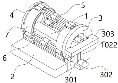
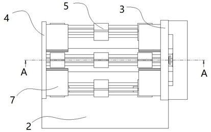
[0033] see Figure 1-7 As shown, the present invention is an automatic pressure tank body welding equipment, which includes a welding workbench 1, a feeding table 2 and a coil group, wherein the coil group includes a limit frame 3, a discharge frame 4 and several coil rollers 5 One side of the welding table 1 is bolted and fixed to the feeding table 2, and the opposite ends of the welding table 1 are respectively welded to the limit frame 3 and the discharge frame 4; the opposite ends of the coil roll 5 are respectively connected to the limit frame 3 and the The discharge rack 4 is linked by bearings;
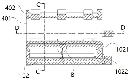
[0034] The welding workbench 1 is a "U"-shaped frame structure, including an upper beam and a lower beam. The upper beam and the lower beam have the same structure, and there is a gap between the two for transferring steel plates; the limit frame 3 and the discharge frame 4 are both It is an annular plate structure, wherein the discharge frame 4 includes an inner ring 401 and ...
Embodiment 2
[0041] Preferably, a controller is installed in the welding workbench 1, and the winding motor 301, the adjusting motor 302 and the hydraulic press 303 are all electrically connected to the controller; The work of the components; two induction grooves 105 are opened on the lower surface of the upper beam, and the two induction grooves 105 are respectively arranged on both sides of the chute 101; the inner surface of the induction groove 105 is welded with an electrode bolt 1051 through a spring; the left and right electrode bolts 1051 are electrically connected, And the electrode plug 1051 is electrically connected with the controller;
[0042] Among them, the electrode plug 1051 is a metal conductive column. The distance between the left and right electrode plugs 1051 and the contact point of the steel plate is the shortest during the steel plate transmission process, and the resistance is the smallest. At this time, the winding motor 301 is working, and the adjusting motor 30...
Embodiment 3
[0044] It needs to be further explained that, as mentioned above, in the assembly and welding of the pressure tank body, in addition to the straight line welding process of winding the steel plate into a cylindrical structure and then fixing it, the internal partition plate and other components of the tank body During the assembly of the tank, it is usually necessary to fit the inner wall of the tank to carry out arc welding work, so when using the present invention, the above-mentioned working method is only the process of welding the tank body, and when it involves welding parts such as partitions inside the tank body, The control method can be modified through the controller. After the straight line welding of the cylinder body is completed, the position of the welding torch 104 is adjusted to the assembly welding position of the internal components by adjusting the motor 302, and then the winding motor 301 is started to make the cylinder body in a rotating state. After the ...
PUM
 Abstract
Description
Claims
Application Information
 - R&D
- Intellectual Property
- Life Sciences
- Materials
- Tech Scout
- Unparalleled Data Quality
- Higher Quality Content
- 60% Fewer Hallucinations
Browse by: Latest US Patents, China's latest patents, Technical Efficacy Thesaurus, Application Domain, Technology Topic, Popular Technical Reports.
© 2025 PatSnap. All rights reserved.Legal|Privacy policy|Modern Slavery Act Transparency Statement|Sitemap|About US| Contact US: help@patsnap.com