Vulcanizing mold for air spring leather bag

An air spring and vulcanization mold technology, applied in the field of vulcanization molds, can solve the problems of shortened service life of the capsule, many steam circuits, poor heating effect, etc., and achieve the effect of improving the overall efficiency, good heating effect, and increasing contact area.

Pending Publication Date: 2021-09-28
玉环协德汽配工业制造有限公司
View PDF1 Cites 0 Cited by
  • Summary
  • Abstract
  • Description
  • Claims
  • Application Information

AI Technical Summary

Problems solved by technology

[0003] For example, the Chinese invention patent application number 202011185365.8, the patent name is a vulcanization mold and vulcanization process for an air spring bladder. Attached to the air spring bladder, the capsule expands when heated and the compartment is compressed when it is attached to the air spring bladder, which causes the capsule to expand under heat and vulcanize under pressure (expansion under pressure) for a long time to become cooling contraction and pressure release contraction, resulting in The service life of the capsule is shortened; 2: After the air spring bladder is put on the mandrel, the upper center guide rod is driven down by the upper center cylinder to move down to the set position, and then the upper base of the mold and the middle mold are driven down together by the clamping cylinder Move to the set position to realize the mold. Therefore, the product is placed from the bottom. In case the middle mold presses the product or the product is not completely placed in the interval cavity, the operator will not know anything
3: The first middle mold has a first heating chamber that can p

Method used


Image

  • Vulcanizing mold for air spring leather bag
  • Vulcanizing mold for air spring leather bag
  • Vulcanizing mold for air spring leather bag

Examples


Embodiment Construction

[0024] Embodiments of the present invention are described in detail below, examples of which are shown in the accompanying drawings, and the embodiments described below by referring to the accompanying drawings are exemplary and are intended to explain the present invention so that the technical solutions of the present invention It is easier to understand and grasp, but cannot be construed as a limitation to the present invention.

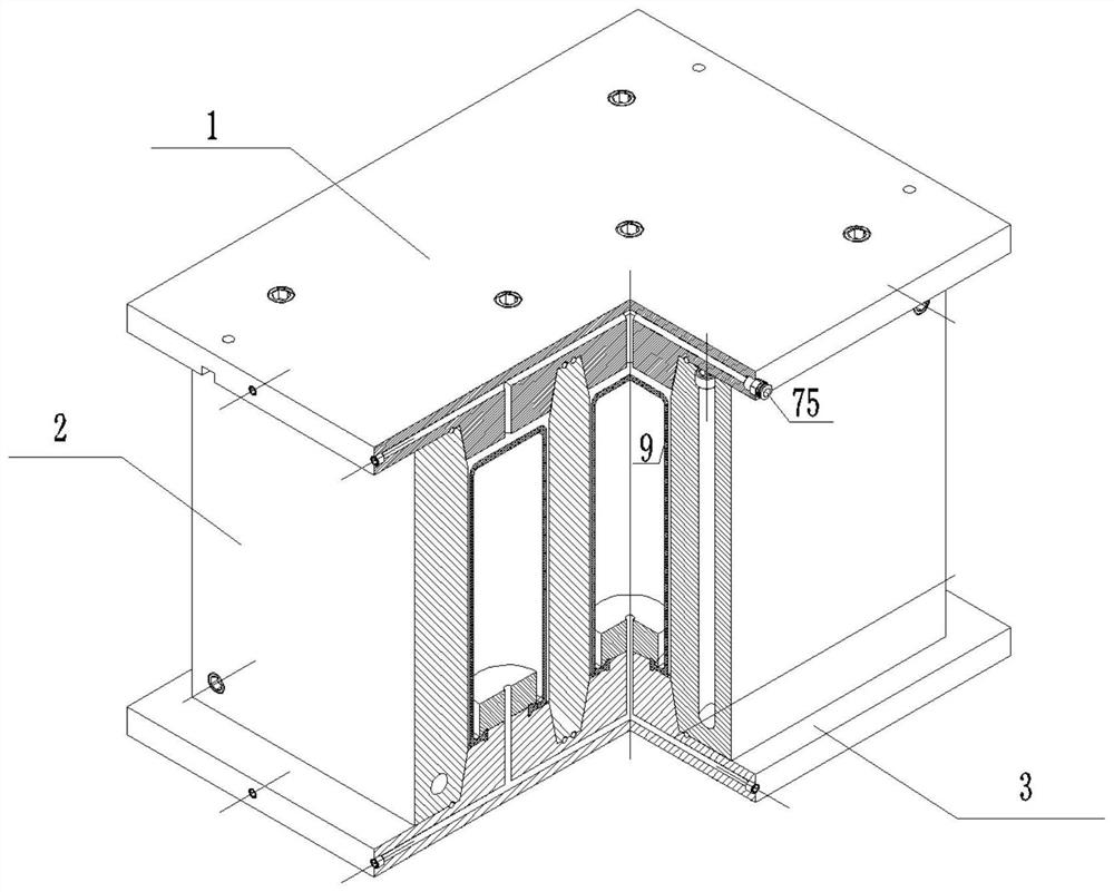
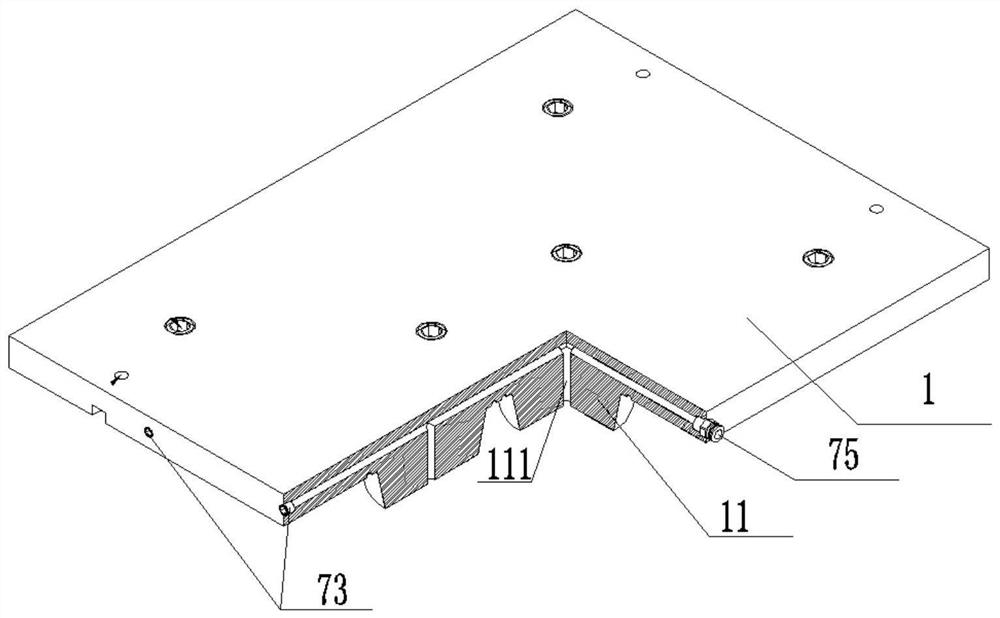
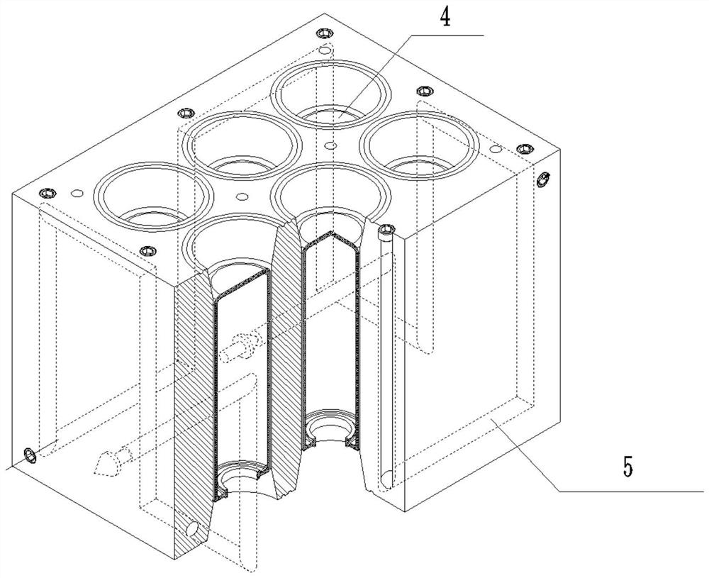
[0025] What is explained here is that the mold of the present invention needs to be used in conjunction with a vulcanizing machine. During use, an air cylinder or an oil cylinder in the prior art is needed to drive the upper mold 1 and the middle mold 2 to move, and the lower mold 3 is fixed on the vulcanizing machine. The column type in the prior art is used to guide up and down movement, and the guide rail type is used to guide left and right movement. At the same time, the steam source is connected to the inlet port 52, the gas outlet port 53 is...


PUM


Abstract

The invention discloses a vulcanizing mold for an air spring leather bag. The vulcanization mold comprises an upper mold, a middle mold and a lower mold, at least one vulcanization hole is formed in the middle mold, the upper mold is provided with a first plunger used for blocking one end of the vulcanization hole, the lower mold is provided with a second plunger used for blocking the other end of the vulcanization hole, a heating pipeline is arranged in the middle mold, a capsule is in a straight tube shape, one end is sealed, the other end is fixed to the second plunger in a sealed mode, a vulcanization chamber is formed among the first plunger, the second plunger, the inner wall of the vulcanization hole and the outer wall of the capsule, and the air spring leather bag is arranged outside the capsule in a sleeving mode and is located in the vulcanization chamber; a vacuumizing header pipe is arranged in the upper mold and communicates with the vulcanizing chamber; and an air charging and exhausting pipeline is arranged in the lower mold and communicates with the interior of the capsule. The mold is simple in structure and high in practicability.

Description

technical field [0001] The invention relates to the field of vulcanization molds, in particular to a vulcanization mold for an air spring bladder. Background technique [0002] In order to quickly attenuate the vibration of the frame and the cab of the vehicle body and improve the ride comfort and comfort of the car, the suspension system of the car is generally equipped with an air spring bag to reduce vibration, and the air spring bag is widely used in the car. [0003] For example, the Chinese invention patent application number 202011185365.8, the patent name is a vulcanization mold and vulcanization process for an air spring bladder. Attached to the air spring bladder, the capsule expands when heated and the compartment is compressed when it is attached to the air spring bladder, which causes the capsule to expand under heat and vulcanize under pressure (expansion under pressure) for a long time to become cooling contraction and pressure release contraction, resulting i...

Claims


Application Information

Patent Timeline
IPC IPC(8): B29C35/04B29C33/04
CPCB29C35/049B29C33/048
Inventor 李承伟瞿亿波
Owner 玉环协德汽配工业制造有限公司
Why Eureka
Try Eureka