
Ultrasonic-assisted fusing device and fusing method of vacuum ultra-high temperature refractory active material

An active material and ultrasonic technology, applied in furnaces, lighting and heating equipment, crucible furnaces, etc., can solve problems such as damage to ultrasonic equipment, pollution of ultra-high temperature refractory active material alloy melts, etc., to avoid melt pollution and ensure purity. The effect of reducing the degree of segregation at grain boundaries

Active Publication Date: 2022-08-02
HARBIN INST OF TECH
View PDF0 Cites 0 Cited by
  • Summary
  • Abstract
  • Description
  • Claims
  • Application Information

AI Technical Summary

Problems solved by technology

[0007] The purpose of the present invention is to solve the problem that the existing ultrasonic equipment reacts with the ultra-high temperature refractory active material alloy at high temperature, pollutes the ultra-high temperature refractory active material alloy melt, and damages the ultrasonic equipment

Method used


Image

  • Ultrasonic-assisted fusing device and fusing method of vacuum ultra-high temperature refractory active material
  • Ultrasonic-assisted fusing device and fusing method of vacuum ultra-high temperature refractory active material
  • Ultrasonic-assisted fusing device and fusing method of vacuum ultra-high temperature refractory active material

Examples


specific Embodiment approach 1

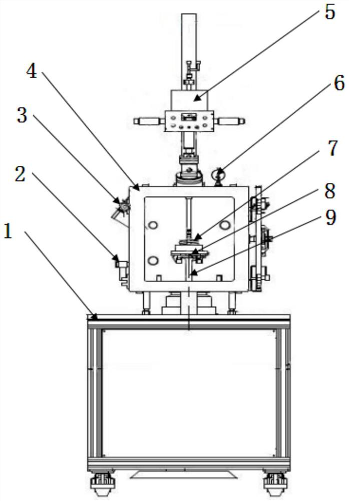
[0029] Embodiment 1: Combining Figure 1 to Figure 3 Illustrating this embodiment, this embodiment includes a movable operating table 1; it also includes a furnace body 4, an observation port 3, a non-consumable arc furnace 5, a pressure gauge 6, a water-cooled copper crucible 8 and an ultrasonic generator 9. The furnace body 4 is installed on the movable operating table 1, the ultrasonic generator 9 is vertically installed on the bottom end surface of the furnace body 4, the water-cooled copper crucible 8 is installed on the ultrasonic generator 9, the raw material 7 is arranged on the water-cooled copper crucible 8, The consumable electric arc furnace 5 vertically passes through the top of the furnace body 4 and extends into the interior of the furnace body 4. There is a distance of 1-20 mm between the lower end of the non-consumable electric arc furnace 5 and the raw material 7, and the observation port 3 is installed On the side wall of the furnace body 4 , a pressure gaug...

specific Embodiment approach 2

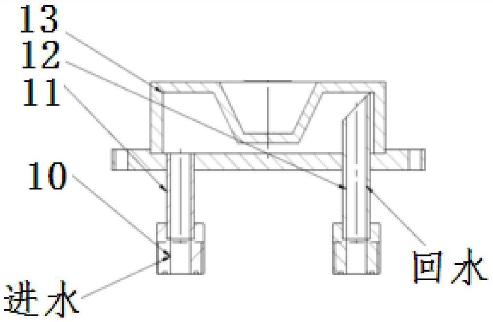
[0030] Specific implementation mode 2: Combining figure 2 Illustrating this embodiment, the water-cooled copper crucible 9 of this embodiment includes a load crucible 13 , a water inlet pipe 11 , a water outlet pipe 12 and two water inlet and outlet joints 10 , and a water inlet pipe 11 and a water outlet pipe 12 are respectively installed at the lower ends of the load crucible 13 . , the bottom ends of the water inlet pipe 11 and the water outlet pipe 12 are respectively installed with a water inlet and outlet joint 10 . This arrangement facilitates water cooling of the crucible. Other components and connection relationships are the same as in the first embodiment.

specific Embodiment approach 3

[0031] Specific implementation three: combination figure 2 Illustrating this embodiment, the load crucible 13 , the water inlet pipe 11 , the water outlet pipe 12 and the two water inlet and outlet joints 10 in this embodiment are all made of red copper. In this way, the overall material of the water-cooled copper crucible in this embodiment is red copper, and cooling water flows through the copper crucible; other compositions and connection relationships are the same as in the first or second embodiment.


PUM

PropertyMeasurementUnit
melting pointaaaaaaaaaa
compressive strengthaaaaaaaaaa
sizeaaaaaaaaaa

Abstract

An ultrasonic-assisted fusing device and a fusing method for vacuum ultra-high temperature refractory active materials relate to a fusing device and a fusing method. The invention solves the problem that the existing ultrasonic equipment reacts with the ultra-high temperature refractory active material alloy at high temperature, pollutes the ultra-high temperature refractory active material alloy melt, and damages the ultrasonic equipment. The ultrasonic generator of the present invention is installed in the furnace body, the water-cooled copper crucible is installed on the ultrasonic generator, the raw material is installed on the water-cooled copper crucible, the non-consumable electric arc furnace extends through the furnace body into the furnace body, and the pressure gauge is installed in the furnace body on the upper end face and communicates with the inside of the furnace body. The non-consumable arc gun is fed into single-phase alternating current for heating; the power of the non-consumable arc gun is reduced, and ultrasonic waves are introduced into the molten raw materials in the water-cooled copper crucible; after the ultrasonic treatment is completed, the power is reduced to a minimum, Then turn off the power. The invention is used for ultrasonic-assisted fusing of vacuum ultra-high temperature refractory active materials.

Description

technical field [0001] The invention relates to an ultrasonic-assisted fusing device and a fusing method, in particular to an ultrasonic-assisted fusing device and fusing method for regulating the microstructure of titanium-aluminum, niobium-silicon, and high-entropy alloys and improving mechanical properties. Background technique [0002] As a new melt processing technology, ultrasonic wave is pollution-free and high-efficiency, which meets the requirements of current science and technology and social development for environmentally friendly and recyclable materials. In order to introduce ultrasonic waves as mechanical waves into the melt of ultra-high temperature refractory active materials, there must be a conductive medium in the middle. According to the difference of the medium, it can be divided into direct introduction and indirect introduction. Direct introduction means that the ultrasonic tool head directly acts on the melt and indirectly. Introduction means that th...

Claims


Application Information

Patent Timeline
Patent Type & Authority Patents(China)
IPC IPC(8): C22C1/02C22C14/00C22F3/00F27B14/08F27B14/10
CPCC22C1/02C22C14/00C22F3/00F27B14/08F27B14/10
Inventor 陈瑞润方虹泽王琪丁鑫王亮苏彦庆郭景杰
Owner HARBIN INST OF TECH
Learn More